8
A09276 A09277
RVS/Heat Stage 2 O/W2/B
Heat Stage 1 W/W1
Compressor Low Y1
Compressor High Y/Y2
Fan G
24VAC Hot Heating Rh
24VAC Hot Cooling Rc
Dry Contact 1 D1
Dry Contact 2 D2
24VAC Common C
Humidify HUM
Outdoor Air Temp OAT
Remote Room Sensor RRS
OAT/RRS Return
SRTN
SRTN
Humidifier Solenoid
Valve
O
Y1
W1
G
W2
C
Y2
Y1
Y/Y2
R
C
DH
REMOVE J2
JUMPER FOR
HEAT STAGING
REMOVE J1 FOR
DEHUMIDIFY
MODES
Two-Stage
Air Conditione
Thermidistat
Variable Speed
Fan Coil
TWO-STAGE
AIR CONDITIONER
THERMIDISTAT
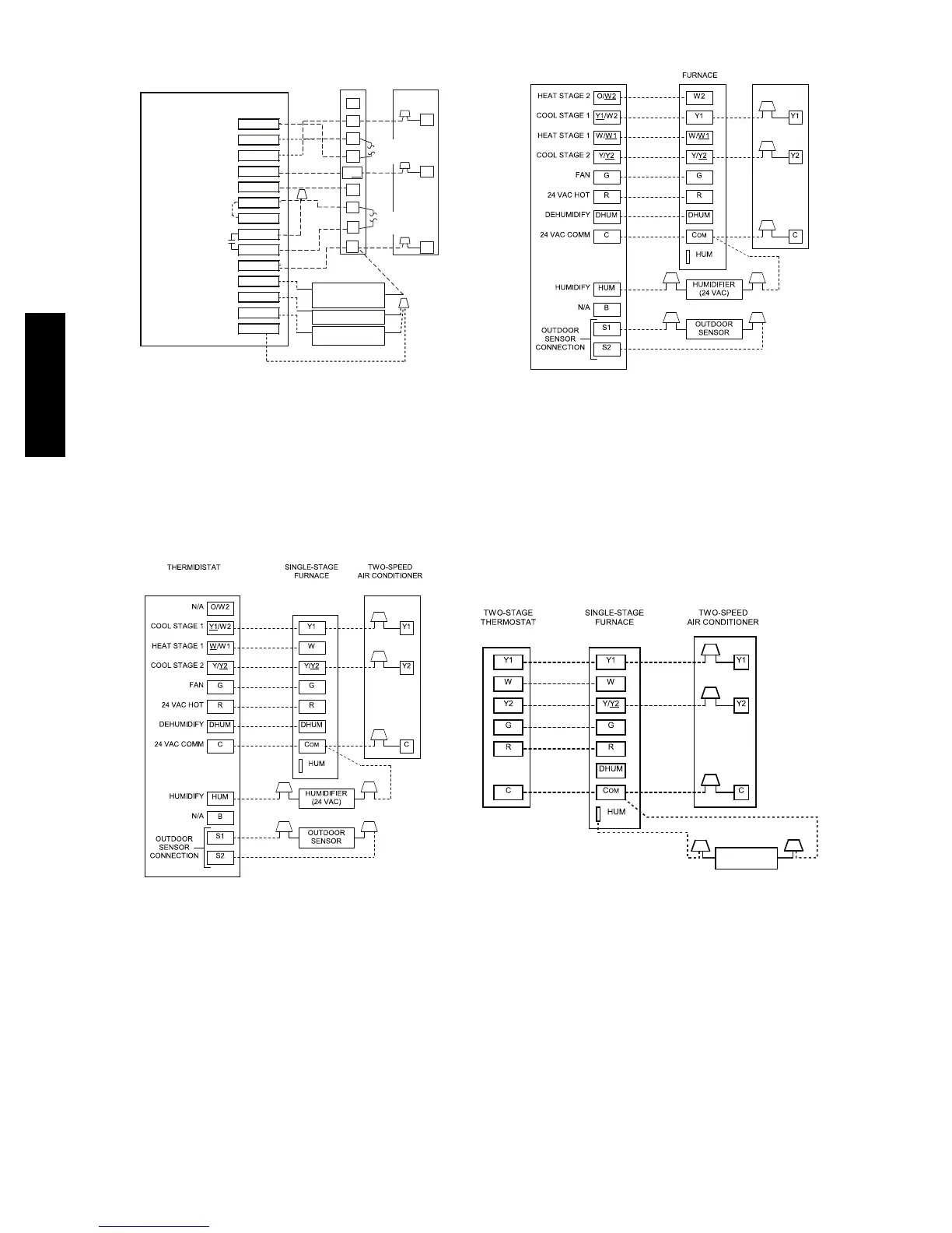
T h e r m i d i s t a t M o d e l s T 6 --- P R H --- 0 1 & T P --- N R H --- 0 1
w/ Variable Speed Fan Coil & 2 ---Stage Air Conditioner
Thermidistat Model TSTATBBPRH01 ---B
w/ Variable Speed Furnace & 2---Stage Air Conditioner
Fig. 6 -- Thermidistat Wiring with 2--Stage Puron refrigerant Air Conditioner
A09278
Single Stage Furnace with 2--- Stage Air Conditioner
A09279
2 --- S t a g e T h e r m o s t a t w i t h S i n g l e --- S t a g e Fu r n a c e a n d
2 ---Stage Air Conditioner
HUMIDFIER
(24VAC)
Fig. 7 -- Generic Wiring Diagrams
(See Thermostat Installation Instruction for specific unit combinations)
127A