EasyManua.ls Logo

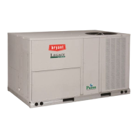
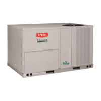
Bryant 580J*04--12 User Manual

Bryant 580J*04--12
73 pages
To Next Page IconTo Next Page
Page #1 background imageLoading...
Page #1 background image
580J*04--12
NOMINAL 3 TO 10 TONS
WITH PURONr (R410A) REFRIGERANT
Service and Maintenance Instructions
TABLE OF CONTENTS
SAFETY CONSIDERATIONS 1....................
UNIT ARRANGEMENT AND ACCESS 2...........
SUPPLY FAN (BLOWER) SECTION 4..............
COOLING 5....................................
PURONR (R410A) REFRIGERANT 8...............
COOLING CHARGING CHARTS 9.................
CONVENIENCE OUTLETS 15....................
SMOKE DETECTORS 16.........................
SENSOR AND CONTROLLER TESTS 19...........
PROTECTIVE DEVICES 22.......................
GAS HEATING SYSTEM 23......................
ECONOMIZER SYSTEMS 33.....................
PRE START--UP 42..............................
START--UP, GENERAL 42........................
OPERATING SEQUENCES 43.....................
FASTENER TORQUE VALUES 45.................
WIRING DIAGRAMS 46.........................
APPENDIX I. MODEL NUMBER SIGNIFICANCE 48.
APPENDIX II. PHYSICAL DATA 49................
APPENDIX III. FAN PERFORMANCE 55...........
APPENDIX IV. ELECTRICAL DATA 65.............
APPENDIX V. WIRING DIAGRAM LIST 70.........
APPENDIX VI. MOTORMASTER SENSOR
LOCATIONS 71.................................
UNIT START-UP CHECKLIST 73..................
SAFETY CONSIDERATIONS
Installation and servic ing of air-conditioning e quipment
can be hazardous due to system pressure and electrical
compone nts. Only trained and qualified service personnel
should install, repair, or service air-conditioning
equipment. Untrained personnel can perform the basic
maintenance functions of replacing filters. Trained service
personnel should perform all other operations.
When working on air-conditioning equipme nt, observe
precautions in the literature, tags and labels attached to
the unit, and other safety precautions that may apply.
Follow all safety codes. Wear safety glasse s and work
gloves. Use quenching cloth for unbrazing operations.
Have fire extinguishers available for all brazing
operations.
Follow all safety codes. Wear safety glasse s and work
gloves. Use quenching cloth for brazing operations. Have
fire extinguisher available. Read these instructions
thoroughly and follow all warnings or cautions attached to
the unit. Consult local building codes and National
Electrical Code (NEC) for special requirements.
Recognize safety information. This is the safet y--alert
symbol
. When you see t his symbol on the unit and in
instructions or manuals, be alert to the potential for
personal injury.
Understand the signal words DANGER, WARNING, and
CAUTION. These words are used with the safety--alert
symbol. DANGER identifies the most serious hazards
which will result in severe personal injury or death.
WARNING signifies a hazard which could result in
personal injury or death. CAUTION is used to identify
unsafe practices which may result in minor personal
injury or product and property damage. NOTE is used to
highlight suggestions which will result in enhanced
installation, reliability, or operation.
FIRE, EXPLOSION HAZARD
Failure to follow this warning could result in
personal injury, death and/or property damage.
Refer t o the Users Information Manual provided
with this unit for more details.
Do not store or use gasoline or other fla mmable
vapors and liquids in the vicinity of this or any other
appliance.
What to do if you smel l gas:
DO NOT try to light any appliance.
DO NOT touch any electrical switch, or use any
phone in your building.
IMMEDIATELY call your gas supplier from a
neighbors phone. Follow the gas suppliers
instructions.
If you cannot reach your gas supplier, call the fire
depart ment.
!
WARNING
Question and Answer IconNeed help?

Do you have a question about the Bryant 580J*04--12 and is the answer not in the manual?

Bryant 580J*04--12 Specifications

General IconGeneral
Model580J*04--12
SEER RatingUp to 17
RefrigerantR-410A
Stages1
EfficiencyHigh
Operating Voltage208/230V
Phase1
Sound Level (Outdoor)72 dB
Compressor TypeSingle Stage

Summary

Safety Considerations

General Safety Precautions

Installation and servicing of AC equipment requires trained personnel for safety.

Safety Symbols and Signal Words

Explains safety-alert symbol and signal words like DANGER, WARNING, CAUTION.

Fire and Explosion Hazard Warning

Warning about flammable vapors and gas leak procedures.

Unit Arrangement and Access

Routine Maintenance

Lists monthly/quarterly checks and seasonal maintenance tasks.

Seasonal Maintenance

Lists tasks for seasonal checks like fan motor bolts, compressor bolts.

Economizer or Outside Air Damper

Air Filters and Screens

Details on return air filters and outside air screens, cleaning and replacement.

Supply Fan (Blower) Section

Belt Maintenance

Checking belt condition, tension, and replacement procedures.

Adjustable-Pitch Pulley on Motor

How to adjust the motor pulley for fan speed changes and pulley alignment.

To Change Fan Speed

Steps to adjust the motor pulley to change fan speed.

Cooling

Condenser Coil Maintenance and Cleaning

Recommendations for routine cleaning of condenser coil surfaces to maintain operation.

Routine Cleaning of Coil Surfaces

Totaline Environmentally Sound Coil Cleaner

Details on using Totaline coil cleaner for effective and safe coil cleaning.

Evaporator Coil

Cleaning the Evaporator Coil

Step-by-step procedure for cleaning the evaporator coil.

Puron® (R410A) Refrigerant

Refrigerant Charge

Information on refrigerant charge amount and procedures.

Compressor

Lubrication

Information on compressor oil type and handling due to its hygroscopic nature.

Compressor Rotation

How to check and correct compressor rotation direction for 3-phase units.

Troubleshooting Cooling System

Compressor and Condenser Fan Will Not Start

Lists causes and remedies for compressor and fan not starting.

Compressor Will Not Start But Condenser Fan Runs

Lists causes and remedies when compressor won't start but fan runs.

Compressor Cycles (other than normally satisfying thermostat)

Lists causes and remedies for compressor cycling issues.

Compressor Operates Continuously

Lists causes and remedies for continuous compressor operation.

Smoke Detectors

System Overview

Primary function of the smoke detector system is to shut down the unit.

Sensor and Controller Tests

Sensor Alarm Test

Procedure to test the sensor's ability to signal an alarm state using a magnet.

Controller Alarm Test

Procedure to test the controller's ability to initiate and indicate an alarm state.

Alarm State

Alarm State Description

What happens when the smoke detector signals an alarm state.

Trouble State Description

Conditions that lead to the smoke detector entering a trouble state.

Protective Devices

Compressor Protection

Details on compressor overcurrent, overtemperature, high pressure, and low pressure protection.

Evaporator Freeze Protection

Information on the temperature switch for evaporator freeze protection.

Supply (Indoor) Fan Motor Protection

Protection devices for the supply fan motor, including internal and Thermix types.

Gas Heating System

General Gas Heating System Description

Overview of the heat exchanger system, burners, and safety switches.

Burners and Igniters

Main Burners Inspection

Inspecting main burners for deterioration or blockage at the start of heating season.

Unit Control Box/IGC Location

Gas Valve Adjustment

Procedure for adjusting gas valve pressure settings for heating.

Burner Ignition

Unit ignition system, IGC, and LED error code interpretation.

Spark Adjustment

Table 9 – IGC Connections

Table 13 – Heating Service Analysis

Burners Will Not Ignite

Lists causes and remedies for burners failing to ignite.

Inadequate Heating

Lists causes and remedies for insufficient heating performance.

Poor Flame Characteristics

Lists causes and remedies for improper burner flame characteristics.

Economizer Systems

Table 15 – EconoMi$er IV Input/Output Logic

EconoMi$er IV Standard Sensors

Fig. 44 - Supply Air Sensor Location

Outdoor Dry Bulb Changeover

How outdoor dry bulb temperature controls damper position for free cooling.

Fig. 49 - Enthalpy Changeover Setpoints

Outdoor Enthalpy Changeover

Setting outdoor enthalpy changeover using potentiometer for cooling.

Differential Enthalpy Control

Using two enthalpy sensors for differential enthalpy control for cooling.

Fig. 50 - EonoMi$er IV Control

Indoor Air Quality (IAQ) Sensor Input

Using IAQ sensor for demand control ventilation based on CO2 levels.

Demand Controlled Ventilation (DCV)

DCV Operation and Setpoints

How DCV operates and how to set damper positions for ventilation.

Table 17 - EconoMi$er IV Sensor Usage

Wiring Diagrams

Pre-Start-Up

Important safety warnings and checks before unit start-up.

Start-Up, General

Gas Piping Leak Check

Checking gas piping for leaks before operating the unit.

Compressor Rotation Check

Procedure to verify correct compressor rotation direction for 3-phase units.

Cooling Start-up Procedure

Steps to start the unit in cooling mode and check refrigerant charge.

Heating Start-up Procedure

Heating Operation Check

Verifying burner ignition, heating controls, and fan operation.

Fastener Torque Values

Demand Controlled Ventilation (DCV)

How DCV strategy operates with CO2 sensors to control dampers.

Appendix I. Model Number Significance

Model Number Nomenclature

Breakdown of the model number to identify unit specifications.

Appendix II. Physical Data (Cooling)

Refrigeration System Data

Physical data for refrigeration system components like circuits, charge, oil, and pressures.

Appendix II. Physical Data (cont.)

Appendix III. Fan Performance (cont.)

Appendix IV. Electrical Data

3 Tons Electrical Data

Electrical data for 3-ton units, including voltage, RLA, LRA, FLA, and IFM specs.

4 Tons Electrical Data

Electrical data for 4-ton units, including voltage, RLA, LRA, FLA, and IFM specs.

Appendix IV. Electrical Data (cont.)

5 Tons Electrical Data

Electrical data for 5-ton units, including voltage, RLA, LRA, FLA, and IFM specs.

7.5 Tons Electrical Data

Electrical data for 7.5-ton units, including voltage, RLA, LRA, FLA, and IFM specs.

6 Tons Electrical Data

Electrical data for 6-ton units, including voltage, RLA, LRA, FLA, and IFM specs.

8.5 Tons Electrical Data

Electrical data for 8.5-ton units, including voltage, RLA, LRA, FLA, and IFM specs.

10 Tons Electrical Data

Electrical data for 10-ton units, including voltage, RLA, LRA, FLA, and IFM specs.

Appendix IV. Electrical Data (cont.)

Unbalanced 3-Phase Supply Voltage

Appendix V. Wiring Diagram List

Start-Up Checklist

Preliminary Information

Fields for model number, serial number, date, and technician.

Pre-Start-Up

Checklist of pre-start-up inspections and verifications.

Start-Up Electrical and Temperatures

Section for recording electrical and temperature readings during start-up.

Start-Up Pressures and Verifications

Section for recording pressure readings and verifying system parameters.

Related product manuals