EasyManua.ls Logo

Bryant 582K - User Manual

Bryant 582K
24 pages
Print Icon
To Next Page IconTo Next Page
Loading...
Manufacturer reserves the right to discontinue, or change at any time, specifications or designs without notice and without incurring obligations.
Catalog No. 04-53500252-01 Printed in U.S.A. Form IIK-CRECOMZR67-05 Pg 1 12-21 Replaces: IIK-CRECOMZR67-04
Installation Instructions
Part No. CRECOMZR067A01, CRECOMZR069A01, and CRECOMZR071A01
CONTENTS
Page
SAFETY CONSIDERATIONS . . . . . . . . . . . . . . . . . . . 1
. . . . . . . . . . . . . . . . . . . . . . . . . . . . . . . . . . . . . . . . . . . 1
GENERAL . . . . . . . . . . . . . . . . . . . . . . . . . . . . . . . . . . . 2
Accessories List . . . . . . . . . . . . . . . . . . . . . . . . . . . . . 3
Compliance . . . . . . . . . . . . . . . . . . . . . . . . . . . . . . . . . 3
INSTALLATIO
N . . . . . . . . . . . . . . . . . . . . . . . . . . . . . . 4
Instructions for 48/50LC 07-12 Units Only . . . . . . . . 9
Installing Optional HH57AC081 Single Outside Air
Enthalpy Sensor . . . . . . . . . . . . . . . . . . . . . . . . . . 13
Installing Differential Return Air Sensor . . . . . . . . . 14
California’s Title 24 High Temperature Limit
Settings . . . . . . . . . . . . . . . . . . . . . . . . . . . . . . . . . 14
Demand Controlled Ventilation (DCV) . . . . . . . . . . . 14
Re
mote (Downstairs) Monitoring of Controller’s Fault
Detection and Diagnostics . . . . . . . . . . . . . . . . . . 15
GENERAL W7220 CONTROLLER AND SENSOR
INFORMATION . . . . . . . . . . . . . . . . . . . . . . . . . . . . 16
W7220 Economizer . . . . . . . . . . . . . . . . . . . . . . . . . . 16
User Interface . . . . . . . . . . . . . . . . . . . . . . . . . . . . . . 16
Keypad . . . . . . . . . . . . . . . . . . . . . . . . . . . . . . . . . . . . 16
Using the Keypad with Menus . . . . . . . . . . . . . . . . . 16
Using the Keypad with Settings and Parameters . . 16
Menu Structure . . . . . . . . . . . . . . . . . . . . . . . . . . . . . 16
PROGRAM
MING W7220 CONTROLLER . . . . . . . . . 16
Setpoints . . . . . . . . . . . . . . . . . . . . . . . . . . . . . . . . . . 16
System Setup . . . . . . . . . . . . . . . . . . . . . . . . . . . . . . 17
Checkout Tests . . . . . . . . . . . . . . . . . . . . . . . . . . . . . 21
W7220 Economizer Module Wiring . . . . . . . . . . . . . 22
Time-out and Screen Saver . . . . . . . . . . . . . . . . . . . 22
START-UP AND OPERATION
. . . . . . . . . . . . . . . . . . 22
Cooling, Unit with EconoMi$er®
X . . . . . . . . . . . . . 22
Heating with EconoMi$er® X . . . . . . . . . . . . . . . . . . 22
TROUBLESHOOTING . . . . . . . . . . . . . . . . . . . . . . . . 24
Power Loss (Outage or Brownout) . . . . . . . . . . . . . 24
Alarms . . . . . . . . . . . . . . . . . . . . . . . . . . . . . . . . . . . . 24
Clearing Alarms . . . . . . . . . . . . . . . . . . . . . . . . . . . . . 24
SAFETY CONSIDERATIONS
Installation of this accessory can be hazardous due to system
pressures, electrical components, and equipment location (such as
a roof or elevated structure). Only trained, qualified installers and
service technicians should install, start-up, and service this
equipment.
When installing this accessory, observe precautions in the
literature, labels attached to the equipment, and any other safety
precautions that apply:
Follow all safety codes
Wear safety glasses and work gloves
Use care in handling and installing this accessory
It is important to recognize safety information. This is the safety-
alert symbol: . When you see this symbol on the unit and in
instructions or manuals, be alert to the potential for personal
injury.
Understand the signal words DANGER, WARNING, CAUTION,
and NOTE. These words are used with the safety-alert symbol.
DANGER identifies the most serious hazards which will result in
severe personal injury or death. WARNING signifies hazards
which could result in personal injury or death. CAUTION is used
to identify unsafe practices, which may result in minor personal
injury or product and property damage. NOTE is used to highlight
suggestions which will result in enhanced installation, reliability,
or operation.
WARNING
ELECTRIC SHOCK HAZARD
Failure to follow this warning could result in personal injury,
property damage, or death.
Before performing service or maintenance operations on unit,
always turn off main power switch to unit and install lock(s)
and lockout tag(s). Unit may have more than one power
switch. Ensure electrical service to rooftop unit agrees with
voltage and amperage listed on the unit rating plate.
If any wiring changes are required, first be sure to remove
power from the economizer module before starting work. Pay
particular attention to verifying the power connection (24 vac).
CAUTION
PERSONAL INJURY HAZARD
Failure to follow this caution may result in personal injury.
Sheet metal parts may have sharp edges or burrs. Use care and
wear appropriate protective clothing, safety glasses and gloves
when handling parts and servicing air conditioning equipment.
CAUTION
PERSONAL INJURY HAZARD
Failure to follow this caution can result in personal injury and
damage to the unit.
Cover the duct opening as a precaution so objects cannot fall
into the return duct opening. Be sure to remove the cover when
installation is complete.
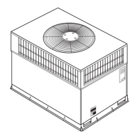
Small Rooftop Units
3 to 12.5 Tons
(48/50LC 14 Not Included)
Accessory Ultra Low Leak Vertical EconoMi$er
®
X

Questions and Answers

Bryant 582K Specifications

General IconGeneral
BrandBryant
Model582K
CategoryAir Conditioner
LanguageEnglish

Summary

SAFETY CONSIDERATIONS

Electric Shock Hazard Warning

Warning about electrical shock during service or maintenance operations.

Personal Injury Hazard Cautions

Cautions regarding sharp edges, burrs, and falling objects during installation.

GENERAL EconoMi$er X System Overview

System Technology and Capabilities

Explanation of the EconoMi$er X system's technology and operational features.

Unit Compatibility Charts

Tables listing compatible unit models for EconoMi$er X part numbers.

Package Contents and Sensor Usage

Table 4 - Package Contents

Lists the components included in the EconoMi$er X installation kit.

Table 5 - Sensor Requirements

Details sensor requirements for various economizer applications.

Regulatory Compliance

California Title 24 and ASHRAE 90.1

Economizer compliance with energy codes and standards for leakage and diagnostics.

INSTALLATION PROCEDURES

Unit Preparation and Component Mounting

Steps for preparing the unit and mounting controller and sensor components.

Wiring and Harness Connections

Instructions for connecting various wires, harnesses, and terminals.

Hood and Filter Assembly

Steps for installing the EconoMi$er X hood and aluminum filters.

Installation Visual Aids

Fig. 3 & 4 - EconoMi$er X Assembly and Flange Installation

Illustrations showing the EconoMi$er X assembly and flange installation.

Fig. 6, 7 & 8 - Control Box and CTB Connections

Diagrams for control box mounting and CTB plug connections.

Electrical Connections Detail

Fig. 9 & 10 - Plug Connections

Visual guides for connecting 10-pin plugs and to the Central Terminal Board.

Fig. 11 & 12 - Terminal Board Wiring

Shows connecting specific wires to the CTB and the ground wire.

Harness and Sensor Wiring

Fig. 13 & 15 - Harness and Sensor Connections

Instructions for connecting the 48TMHSRSE--A20 harness and the mixed air sensor.

Fig. 14 & 16 - Wire Routing and Connections

Details on routing wires and connecting specific wires in the blower section.

Hood Assembly and Performance Data

Fig. 17 & 20 - Hood Installation

Diagrams for assembling and installing the EconoMi$er X hood and access door.

Fig. 21 & 22 - Performance Graphs

Graphs illustrating barometric relief flow capacity and return air pressure drop.

Wiring Diagrams and Specific Unit Instructions

Fig. 23 - Typical Economizer Wiring

Shows the typical wiring diagram for the EconoMi$er X system.

48;50 LC 07-12 Unit Wiring

Specific wiring instructions and considerations for 48/50LC 07-12 unit models.

Specific Unit Wiring Components

Fig. 24 - Harness Removal

Illustration showing the removal of the factory-attached W7220 controller harness.

Fig. 26 - 48;50 LC Controller Harness

Photograph of the W7220 controller harness for 48/50LC units.

48;50 LC 07-12 Harness Diagram

Fig. 27 - Wiring Diagram for 48;50 LC Units

Detailed wiring diagram of the 48LCHSRADH--A00 harness for 48/50LC units.

Economizer Wiring Diagrams

Fig. 28 - Typical Wiring for 48;50 LC Units

Comprehensive wiring diagram specific to 48/50LC 07-12 units.

Optional Enthalpy Sensor Installation

Fig. 29 & Table 7 - Enthalpy Curves and Limits

Enthalpy curve boundaries and high limit curves for sensor settings.

Table 8 - HH57 AC081 Sensor Dip Switches

Guide for configuring the HH57AC081 sensor using its dip switches.

Differential Return Sensor & California Title 24

Fig. 31 - Differential Return Sensor Wiring

Wiring diagram for installing the differential return air sensor.

Table 9 - California Title 24 Temperature Limits

Region-specific temperature limits required by California Title 24.

Fig. 32 - CO2 Sensor Wiring

Connections for a CO2 sensor used for Demand Controlled Ventilation (DCV).

Remote Fault Detection and Diagnostics

Fig. 33 - Thermostat for Remote FDD

Wiring example for using a thermostat to monitor controller faults remotely.

Fig. 34 - Annunciator Light for Remote FDD

Wiring example for an annunciator light to indicate controller faults.

W7220 Controller Information

User Interface and Keypad Operation

Details on the controller's LCD display, navigation buttons, and keypad functions.

Navigating Menus and Settings

Instructions for using the keypad to navigate menus and adjust controller settings.

Controller Setpoints Explained

Explanation of various setpoints like MAT, LOW T LOCK, DRYBULB SET, ENTH CURVE, MIN POS.

Controller Configuration and Setup

System Setup Parameters

Configuration options for INSTALL, EQUIPMENT, AUX2 IN, FAN TYPE, AUX1 OUT, and OCC.

Table 10 - Standard Controller Settings

Summary of default and configurable settings for 1 or 2 speed units.

W7220 Controller Menu Structure

Status Menu Parameters

Detailed descriptions for parameters found in the 'STATUS' menu.

Setpoints Menu Parameters

Detailed descriptions for parameters found in the 'SETPOINTS' menu.

W7220 Controller Menu Structure (cont.)

Setpoints Menu Parameters (Continued)

Further details on 'SETPOINTS' menu parameters, including ventilation limits.

Advanced Setup Menu Parameters

Detailed descriptions for parameters in the 'ADVANCED SETUP' menu, including calibration.

W7220 Controller Menu Structure (cont.)

System Setup Menu Parameters

Details for parameters within the 'SYSTEM SETUP' menu, like airflow and freeze protection.

Advanced Setup Menu Parameters (Continued)

More details on 'ADVANCED SETUP' parameters, including 2SP FAN DELAY.

W7220 Controller Menu Structure (cont.)

Checkout Menu Parameters

Parameters available for performing checkout tests on the economizer.

Alarms Menu Parameters

Parameters for viewing and managing system alarms.

Economizer Module Wiring and Operation

Table 12 & 13 - Terminal Block Wiring

Detailed wiring information for the economizer module's left and right terminal blocks.

Start-Up and Operation Modes

Guidance on unit start-up, occupied/unoccupied modes, and cooling operation.

Damper Control for 2-Speed Fan Motors

Table 14 - Damper Position Control

Table showing damper position based on inputs, fan speed, and CO2 sensor presence.

TROUBLESHOOTING AND ALARMS

Power Loss and System Settings

How power outages affect setpoints and the controller's memory.

Alarm Messages and Handling

Information on alarm messages displayed on the LCD and how to clear them.

Common Operating Issues and Solutions

Table addressing common issues, concerns, and their potential causes and remedies.

Related product manuals