22
W7220 Economizer Module Wiring
Use Tables 12 and 13 to locate the wiring terminals for the
economizer module.
Time-out and Screen Saver
When no buttons have been pressed for 10 minutes, the LCD
displays a screen saver, which cycles through the Status items.
Each status item displays in turn and cycles to the next item after
5 seconds.
START-UP AND OPERATION
Cooling, Unit with EconoMi$er
®
X
For Occupied mode operation of EconoMi$er X system, there
must be a 24-v signal at terminals R and OCC (provided through
PL6-3 from the unit’s IFC coil). Removing the signal at OCC
places the EconoMi$er X control in Unoccupied mode. See
Table 14 for Damper Position Control.
During Occupied mode operation, indoor fan operation will be
accompanied by economizer dampers moving to Minimum
Position setpoint for ventilation. If indoor fan is off, dampers will
close. During Unoccupied mode operation, dampers will remain
closed unless a Cooling (by free cooling) or DCV demand is
received.
When free cooling using outside air is not available, the unit
cooling sequence will be controlled directly by the space
thermostat. Outside air damper position will be closed or
Minimum Position as determined by Occupancy mode and fan
signal.
When free cooling is available as determined by the appropriate
changeover command (dry bulb, outdoor enthalpy, differential dry
bulb or differential enthalpy), a call for cooling (Y1 closes at the
thermostat) will cause the economizer control to modulate the
dampers open and closed to maintain the unit supply air
temperature. Default mixed air temperature is 53°F, with a range
of 38°F to 70°F. Compressor will not run.
Should 100% outside air not be capable of satisfying the space
temperature, space temperature will rise until Y2 is closed. The
economizer control will call for compressor operation. Dampers
will modulate to maintain MAT at set point concurrent with
Compressor 1 operation. The “Low T Lock” setting (default 32°F)
will lock out compressor operation when outside air temperature
is below setpoint.
When space temperature demand is satisfied (thermostat Y1
opens), the dampers will return to Minimum Damper position if
indoor fan is running or fully closed if fan is off.
If accessory power exhaust is installed, the power exhaust fan mo-
tors will be energized by the economizer control as the dampers
open above the EXH1 SET setpoint and will be de-energized as
the dampers close below the EXH1 SET setpoint. (For single
speed unit.)
Damper movement from full closed to full open (or vice versa)
will take between 1-1/2 and 2-1/2 minutes.
Heating with EconoMi$er
®
X
During Occupied mode operation, indoor fan operation will be
accompanied by economizer dampers moving to Minimum
Position setpoint for ventilation. If indoor fan is off, dampers
will close. During Unoccupied mode operation, dampers will
remain closed unless a DCV demand is received.
When the room temperature calls for heat (W1 closes), the heating
controls are energized.
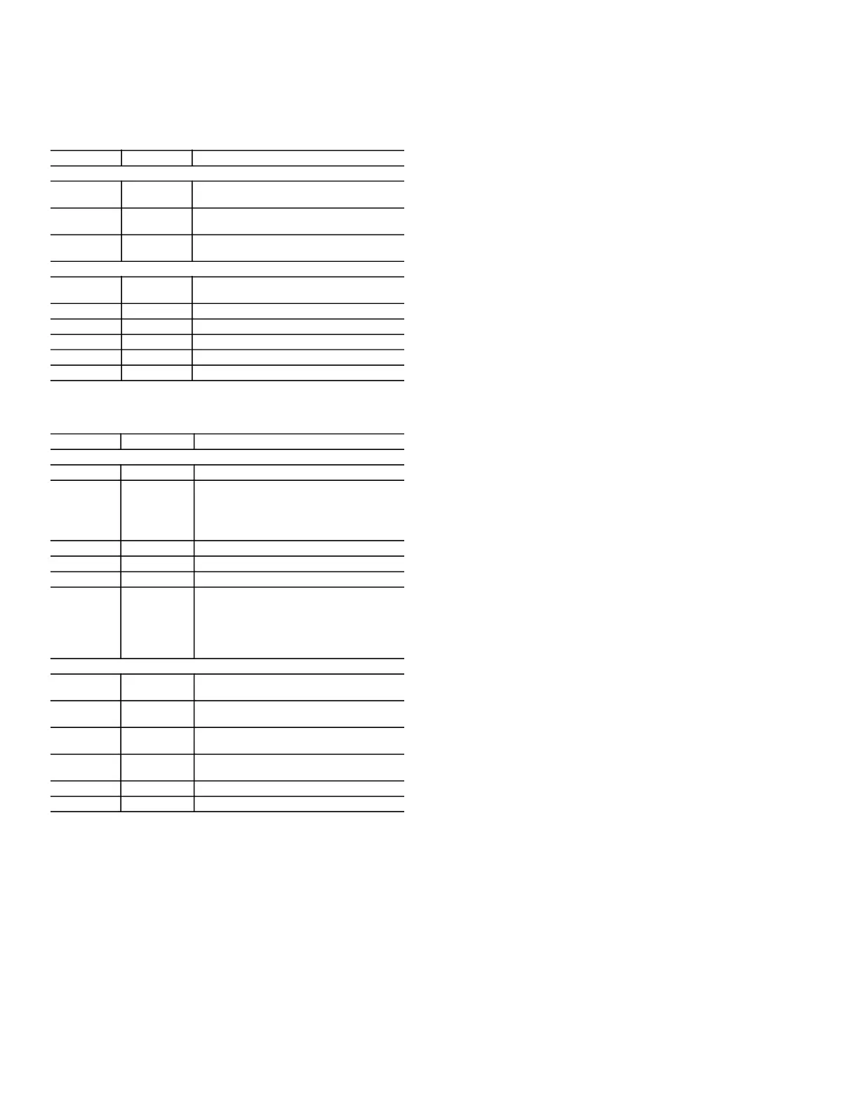
Table 12 — Economizer Module - Left Hand Terminal
Blocks
LABEL TYPE DESCRIPTION
Top Left Terminal Block
MAT
20k NTC
and COM
Mixed Air Temperature Sensor (Polarity
Insensitive Connection)
OAT
20k NTC
and COM
Outdoor Air Temperature Sensor (Polarity
Insensitive Connection)
S-BUS
S-BUS (Sylk
Bus)
Enthalpy Control Sensor
(Polarity Insensitive Connection)
Bottom Left Terminal Block
IAQ 2-10 2-10 vdc
Air Quality Sensor Input (e.g. CO
2
sensor)
IAQ COM COM Air Quality Sensor Common
IAQ 24V 24 vac Air Quality Sensor 24 vac Source
ACT 2-10 2-10 vdc Damper Actuator Output (2-10 vdc)
ACT COM COM Damper Actuator Output Common
ACT 24v 24 vac Damper Actuator 24 vac Source
Table 13 — Economizer Module - Right Hand
Terminal Blocks
LABEL TYPE DESCRIPTION
Top Right Terminal Blocks
na The first terminal is not used.
AUX2 I 24 vac IN
Shut Down (SD) or HEAT (W)
Conventional only
and
Heat Pump Changeover (O-B) in Heat
Pump mode.
OCC 24 vac IN Occupied/Unoccupied Input
E-GND E-GND Earth Ground - System Required
EXH1 24 vac OUT Exhaust Fan 1 Output
AUX1 O 24 vac OUT
Programmable:
Exhaust fan 2 output
or
ERV
or
System alarm output
Bottom Right Terminal Blocks
Y2-I 24 vac IN
Y2 in - Cooling Stage 2 Input from space
thermostat
Y2-O 24 vac OUT
Y2 out - Cooling Stage 2 Output to stage
2 mechanical cooling
Y1-I 24 vac IN
Y1 in - Cooling Stage 2 Input from space
thermostat
Y1-O 24 vac OUT
Y1 out - Cooling Stage 2 Output to stage
2 mechanical cooling
C COM 24
vac Common
R 24 vac 24 vac Power (hot)