Do you have a question about the Bryant 580F and is the answer not in the manual?
Highlights severe risks like fire, explosion, or loss of life if instructions are not followed precisely.
Initial steps involve setting thermostat, closing manual gas valve, and disconnecting electrical power before proceeding.
Includes removing burner access panel, setting gas valve to OFF, waiting, and turning it ON again.
Restores electrical power and sets thermostat to initiate unit startup and burner ignition.
Final step involves setting the room thermostat to the desired temperature for normal operation.
Provides guidance on what actions to take if the main burners fail to ignite or the blower does not operate.
Procedure to shut down the unit begins with setting the thermostat to OFF, closing the external gas valve, and turning off electrical power.
Involves removing the burner access panel and moving the gas valve control to the OFF position.
Covers actions for malfunctions, end-of-season shutdown, and warnings regarding water damage to the unit.
Stresses that maintenance should be handled by qualified personnel and the unit area kept clear of combustibles.
Ensures proper functioning by maintaining clear airflow and required clearances around the unit for ventilation.
Before servicing, turn off gas and electrical power, use lockout tags, and be aware of sharp edges inside the unit.
Detailed steps for inspecting and replacing air filters, including thermostat and power settings.
Provides table for correct filter sizes and warns against operating the unit without filters in place.
Recommends inspection and cleaning by a qualified maintenance person before each heating season.
Periodic checks of fan wheels, housings, belt tension, and fan motor bearings are recommended.
Cleaning of the evaporator and condenser coils should be performed by qualified service personnel.
The drain pan and condensate drain line should be checked and cleaned concurrently with cooling coil checks.
Compressors are factory supplied with the correct type and charge of refrigeration-grade oil.
Warns against inserting objects into the fan and emphasizes keeping the fan free of obstructions.
If discrepancies are found in the operating cycle, contact your dealer for service due to complexity.
Checking refrigerant circuits for leaks requires proper equipment; contact dealer for suspected issues.
Visual inspection of combustion area and vent system before heating season to check for dirt, soot, rust, or scale.
Observe burner flame for bright blue color; call dealer if malfunction is suspected or flame is not blue.
Ensure all unit panels are securely fastened after maintenance to prevent rain entry and airflow disruption.
Checklist for professional service including flue products, combustion passages, gas pipes, coils, drains, ducts, base, casing, wiring, and refrigerant.
Check air filter, return/supply grilles for obstructions when heating or cooling is insufficient.
Troubleshoot unit not operating by checking thermostat settings, electrical supply, fuses, breaker, and gas valve position.
If performance remains unsatisfactory, shut off unit and contact dealer with model and serial numbers.
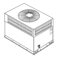
This manual describes the Bryant 580F Single Package Rooftop Gas Heating/Electric Cooling Units, designed for commercial and industrial applications, offering both heating and cooling functionalities.
The Bryant 580F unit is a self-contained rooftop system that provides both gas heating and electric cooling. It features an automatic direct spark ignition system for the gas burners and an induced draft combustion blower, ensuring efficient and safe combustion. The unit is designed to be controlled by a room thermostat, allowing users to set desired temperature settings for both heating and cooling modes. In heating mode, the unit ignites gas burners to produce heat, which is then distributed through the building's ductwork. For cooling, the electric cooling system operates to remove heat from the indoor air. The unit incorporates safety features such as automatic shutdown in case of ignition failure or other malfunctions, and it requires proper ventilation and clearances for safe operation.
Starting the Unit (Heating): To start the heating section, users must first ensure the electrical power to the unit is on and the manual gas valve is open. The room thermostat should be set to the desired temperature and the SYSTEM switch to HEAT or AUTO. The control on the gas valve must be in the ON position. The induced-draft combustion air fan will start, followed by the main gas valve opening and the main burners igniting within 5 seconds. If ignition fails, the unit attempts to reignite after a 22-second delay. After 15 minutes of failed ignition attempts, the unit will lock out, requiring service. It is crucial never to attempt manual ignition of the burners.
Shutting Down the Unit: To shut down the unit, the room thermostat should be set to the lowest temperature and the SYSTEM switch to OFF. The external manual gas valve must be closed, and the electrical supply to the unit turned off, with a lockout tag installed for safety. The burner access panel should be removed, and the control on the gas valve moved to the OFF position before replacing the panel. If the shutdown is due to a malfunction, a qualified dealer should be contacted. If shutting down for the season, electrical power should be restored to ensure the cooling system remains operational during the cooling season.
Safety Precautions: The manual emphasizes several critical safety precautions. Users are warned against storing or using flammable vapors or liquids near the appliance. Improper installation, adjustment, alteration, service, or maintenance can cause injury or property damage. In case of a gas smell, users should not attempt to light any appliance, touch electrical switches, or use any phone in the building. Instead, they should immediately call their gas supplier from a neighbor's phone or the fire department. Before any maintenance, the main power switch must be turned off and a lockout tag installed to prevent electrical shock. It is also explicitly stated not to attempt to ignite gas by hand.
General Maintenance: All maintenance should be performed by skilled, experienced, and qualified personnel. The area around the unit must be kept clear of combustible materials, gasoline, and other flammable liquids and vapors. Adequate clearances (3 ft for sizes 036-072 and 4 ft for sizes 090-150 on flue and condenser sides, 6 in. on other sides, and 5 ft above condenser discharge) are required to ensure proper airflow.
Air Filters: Air filters should be checked every 3 or 4 weeks and cleaned or changed as necessary. The manual provides a table with correct filter sizes for different unit models. To inspect or replace filters, the unit must be shut down, the manual gas valve closed, and electrical power turned off with a lockout tag. The filter access panel is then removed, and filters are pulled out from their track. Filters should always be replaced with the same size and type as originally supplied. Operating the unit without filters can damage the blower motor and/or compressor, reduce efficiency, and pose a fire hazard.
Heat Exchanger: The heat exchanger should be inspected by a qualified maintenance person before each heating season and cleaned when necessary to ensure dependable and efficient operation. This involves removing and reinstalling the gas controls assembly and flue collector box cover, which requires expertise.
Fans, Belts, and Fan Motor: The condition of fan wheels, housings, belt tension, and fan motor shaft bearings should be checked periodically. Lubrication of condenser or evaporator fan bearings or motors is not required.
Evaporator and Condenser Coils: Cleaning of the coils should be done by qualified service personnel as part of annual maintenance.
Condensate Drain: The drain pan and condensate drain line should be checked and cleaned when the cooling coils are serviced.
Compressor: Compressors are factory-supplied with the correct charge of refrigeration-grade oil and typically do not require additional oil.
Condenser Fan: The condenser fan must be kept free of obstructions to ensure proper cooling. Users are warned not to poke sticks, screwdrivers, or other objects into revolving fan blades to prevent severe bodily injury.
Electrical Controls and Wiring: Electrical controls are complex and require proper instrumentation for checking. Any discrepancies in the operating cycle should prompt a call to a dealer.
Refrigerant Circuit: Checking the refrigerant circuit for leaks requires specialized equipment. Inadequate cooling indicates a need to contact a local dealer.
Combustion Area and Vent System: Before each heating season, the combustion area and vent system should be visually inspected for dirt, soot, rust, or scale accumulation, which can lead to loss of efficiency and improper performance. If such accumulations are found, the heating section should not be operated, and a dealer should be called. When observing the burner flame, users should be careful as components can be hot. The flame should be bright blue; any deviation indicates a malfunction requiring dealer service.
Unit Panels: After any maintenance, all panels must be securely fastened to prevent rain entry and maintain correct airflow patterns.
Regular Dealer Maintenance: The manual strongly recommends regular inspections by a properly trained service technician, preferably annually or at least every other year. This comprehensive inspection includes:
Servicing dealers may offer service contracts for seasonal inspections. Complete service instructions are available in the unit Installation, Start-Up and Service Instructions.
| Model | 580F |
|---|---|
| Compressor Type | Single-Stage |
| Refrigerant | R-410A |
| Type | Air Conditioner |
| Cooling Capacity | 2 to 5 tons |