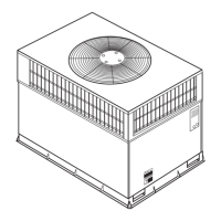
DESCRIPTION
All 588A models feature one piece, compact design and are fully
self-contained units that are prewired, prepiped, and pre-
charged for minimum installation expense. Unit is designed for
easy use in either downflow (vertical) or horizontal applications.
STANDARD FEATURES
FACTORY-ASSEMBLED PACKAGE is a compact, fully self-
contained, gas heating/electric cooling unit that is prewired, pre-
piped, and precharged for minimum installation expense.
588A units are lightweight and available in a variety of standard
heating and cooling sizes with voltage options to meet residen-
tial and light commercial requirements. Unit installs easily on a
rooftop or a ground-level pad.
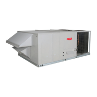
CONVERTIBLE DUCT CONFIGURATION on the 588A is de-
signed for easy use in either downflow or horizontal discharge
applications.
HIGH-EFFICIENCY DESIGN with SEERs (Seasonal Energy Ef-
ficiency Ratios) of 10.0.
DURABLE, DEPENDABLE COMPRESSORS are designed for
high efficiency. Each compressor is hermetically sealed against
contamination to help promote longer life and dependable op-
eration. Each compressor also has vibration isolation to provide
quiet operation. Rotary, reciprocating, or scroll compressors are
used. Compressors have internal high-pressure and overcur-
rent protection.
DIRECT-DRIVE MULTISPEED, PSC (permanent split capaci-
tor) BLOWER MOTOR is standard on all models.
DIRECT-DRIVE, PSC CONDENSER-FAN MOTORS are de-
signed to help reduce energy consumption and provide for cool-
ing operation down to 40 F.
REFRIGERANT SYSTEM is designed to provide dependability.
Liquid refrigerant strainers are used to promote clean, unre-
stricted operation. Each unit leaves the factory with a full refrig-
erant charge. Refrigerant service connections make checking
operating pressures easier.
EVAPORATOR AND CONDENSER COILS are computer-
designed for optimum heat transfer and cooling efficiency. Con-
denser coil is fabricated of copper tube and aluminum fins and
is located inside the unit for protection against damage and for
long life and reliable operation. The condenser coil is internally
mounted and protected by a composite grille.
Copper fin coils for condenser coil are also available by special
order. These coils are recommended in applications where alu-
minum fins are likely to be damaged due to corrosion. Copper
fin coils are ideal for seacoast applications.
MONOPORT INSHOT BURNERS produce precise air-to-gas
mixture, which provides for clean and efficient combustion. The
large monoport on the inshot (or injection type) burners seldom,
if ever, needs cleaning.
WEATHERIZED CABINETS are constructed of heavy-duty,
phosphated, zinc-coated prepainted steel capable of withstand-
ing 500 hours in salt spray. Interior surfaces of the evaporator
compartment are insulated with foil-faced fiberglass to help
keep the conditioned air from being affected by the outdoor am-
bient temperature and provide improved air quality. Conforms to
American Society of Heating, Refrigeration and Air Conditioning
Engineers (ASHRAE) No. 62P. Sloped condensate pan permits
an external drain.
LOW SOUND RATINGS ensure a quiet indoor and outdoor en-
vironment with sound ratings as low as 7.4 bels.
EASY TO SERVICE CABINETS provide easy accessibility to
serviceable components during maintenance and installation.
Rounded corners are an important safety feature, and a high-
quality finish ensures an attractive appearance.
LOW AND HIGH VOLTAGE ELECTRICAL ENTRIES allow low
and high voltage to be brought in either through the duct panel
or rear flue panel.
INTEGRATED GAS CONTROL BOARD provides safe and ef-
ficient control of heating and simplifies troubleshooting through
its built-in diagnostic function.
OPTIONAL BASE RAILS provide holes for rigging and han-
dling as well as an elevated mounting frame that provides struc-
tural support for horizontal installations.
DOWNFLOW OPTIONS is converted for downflow at factory for
easy vertical ductwork connections.
Bryant
Air Conditioning
SINGLE PACKAGE
GAS HEATING/
ELECTRIC COOLING UNITS
Model 588A
Sizes 018-060
1
1
⁄
2
to 5 Tons
Form No. PDS 588A.18.4B