Installation Instructions
NOTE: Read the entire instruction manual before starting the installation.
SAFETY CONSIDERATIONS
IMPORTANT: This appliance shall only be installed by EPA qualified
personnel having appropriate certification. This appliance is not
intended for use by persons (including children) with reduced physical,
sensory or mental capabilities or lack of experience and knowledge,
unless they have been given supervision or instruction concerning use of
the appliance by a person responsible for their safety.
Improper installation, adjustment, alteration, service, maintenance, or
use can cause explosion, fire, electrical shock, or other conditions which
may cause death, personal injury, or property damage. Consult a
qualified installer, service agency, or your distributor or branch for
information or assistance. The qualified installer or agency must use
factory-authorized kits or accessories when modifying this product.
Refer to the individual instructions packaged with the kits or accessories
when installing.
Follow all safety codes. Wear safety glasses, protective clothing, and
work gloves. Use quenching cloth for brazing operations. Have fire
extinguisher available. Read these instructions thoroughly and follow all
warnings or cautions included in literature and attached to the unit.
Consult local building codes and current editions of the National
Electrical Code (NEC) NFPA 70. In Canada, refer to current editions of
the Canadian electrical code CSA 22.1.
Recognize safety information. This is the safety-alert symbol When
you see this symbol on the unit and in instructions or manuals, be alert to
the potential for personal injury. Understand these signal words;
DANGER, WARNING, and CAUTION. These words are used with the
safety-alert symbol. DANGER identifies the most serious hazards which
will result in severe personal injury or death. WARNING signifies
hazards which could result in personal injury or death. CAUTION is
used to identify unsafe practices which would result in minor personal
injury or product and property damage. NOTE is used to highlight
suggestions which will result in enhanced installation, reliability, or
operation.
GENERAL
NOTE: In some cases noise in the living area has been traced to gas
pulsations from improper installation of equipment.
1. This unit is intended to be installed in a location that is 10,000 feet
(3000 meters) above sea level or lower.
2. Locate unit away from windows, patios, decks, etc. where unit
operation sound may disturb customer.
3. Ensure that vapor and liquid tube diameters are appropriate for unit
capacity.
4. Run refrigerant tubes with no bends with centerline bend radius less
than 2.5 times the external pipe diameter.
5. Leave some slack between structure and unit to absorb vibration.
6. When passing refrigerant tubes through the wall, seal opening with
RTV or other pliable silicon-based caulk. (See Fig. 1.)
7. Avoid direct tubing contact with water pipes, duct work, floor
joists, wall studs, floors, and walls.
8. Do not suspend refrigerant tubing from joists and studs with a rigid
wire or strap which comes in direct contact with tubing (see Fig. 1).
9. Ensure that tubing insulation is pliable and completely surrounds
vapor tube.
10. When necessary, use hanger straps which are 1 in. (25 mm) wide
and conform to shape of tubing insulation. (See Fig. 1.)
11. Isolate hanger straps from insulation by using metal sleeves bent to
conform to shape of insulation.
12. Provision shall be made for expansion and contraction of long runs
of piping.
13. Piping and fittings shall be protected as far as possible against
adverse environmental effects. For example, the accumulation of
dirt and debris.
14. Piping should be installed to reduce the likelihood of hydraulic
shock damaging the system.
15. Certified piping and components must be used in order to protect
against corrosion.
16. Flexible pipe elements shall be protected against mechanical
damage, excessive stress by torsion, or other forces. They should be
checked for mechanical damage annually.
17. Piping material, routing, and installation shall be include protection
from physical damage in operation and service, and be in
compliance with the national and local codes and standards of the
installation site.
18. When setting up refrigerant piping, precautions shall be taken to
avoid excessive vibration or pulsation
126S
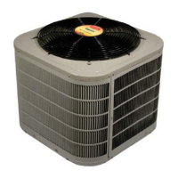
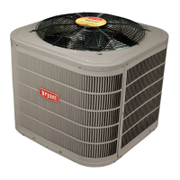
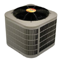
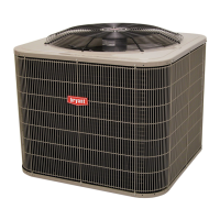
Preferred™ Series Air Conditioners
with Puron® Refrigerant
1-1/2 to 5 Nominal Tons
WARNING
!
ELECTRICAL SHOCK HAZARD
Failure to follow this warning could result in personal injury or death.
Before installing, modifying, or servicing system, main electrical
disconnect switch must be in the OFF position. There may be more than
1 disconnect switch. Lock out and tag switch with a suitable warning
label.
WARNING
!
EXPLOSION HAZARD
Failure to follow this warning could result in
personal injury or death.
Never use air or any gas containing oxygen for leak
testing or operating refrigerant compressors. Never
allow compressor suction pressure to operate in a
vacuum with service valves closed. See service
manual for pump-down instructions.