126S: Installation Instructions
Manufacturer reserves the right to change, at any time, specifications and designs without notice and without obligations.
7
Make Electrical Connections
Be sure field wiring complies with local and national fire, safety, and
electrical codes, and voltage to system is within limits shown on unit
rating plate. Contact local power company for correction of improper
voltage. See unit rating plate for recommended circuit protection device.
NOTE: Operation of unit on improper line voltage constitutes abuse and
could affect unit reliability. See unit rating plate. Do not install unit in
system where voltage may fluctuate above or below permissible limits.
NOTE: Use copper wire only between disconnect switch and unit.
NOTE: Install branch circuit disconnect of adequate size per NEC to
handle unit starting current. Locate disconnect within sight and readily
accessible from unit, per Section 440-14 of NEC. Refer to Product Data
for breaker sizing.
Route Ground and Power Wires
Remove access panel to gain access to unit wiring. Extend wires from
disconnect through power wiring hole provided and into unit control
box.
Connect Ground and Power Wires
This appliance incorporates an earth connection for safety purposes only.
Connect ground wire to ground connection in control box for safety.
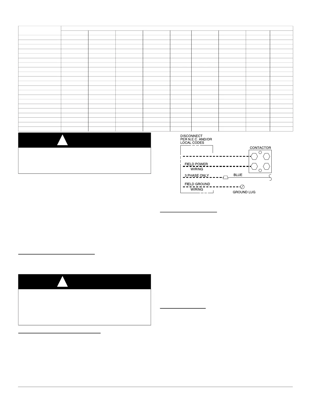
Connect power wiring to contactor as shown in Fig. 6.
A94025
Fig. 6 – Line Connections
Connect Control Wiring
Route 24-v control wires through control wiring grommet and connect
leads to control wiring. Refer to thermostat Installation Instructions for
wiring specific unit combinations (see Fig. 8 ).
Use No. 18 AWG color-coded, insulated (35°C minimum) wire. If
thermostat is located more than 100 ft. (30.48 m) from unit, as measured
along the control voltage wires, use No. 16 AWG color-coded wire to
avoid excessive voltage drop.
All wiring must be NEC Class 2 and must be separated from incoming
power leads.
Use furnace transformer, fan coil transformer, or accessory transformer
for control power, 24v/40va minimum.
NOTE: Use of available 24v accessories may exceed the minimum 40va
power requirement. Determine total transformer loading and increase
the transformer capacity or split the load with an accessory transformer
as required.
Final Wiring Check
IMPORTANT: Check factory wiring and field wire connections to
ensure terminations are secured properly. Check wire routing to ensure
wires are not in contact with tubing, sheet metal, etc.
Compressor Crankcase Heater
When equipped with a crankcase heater, furnish power to heater a
minimum of 24 hr before starting unit. To furnish power to heater only,
set thermostat to OFF and close electrical disconnect to outdoor unit.
A crankcase heater is required if refrigerant tubing is longer than 80 ft.
(24.38 m) or when outdoor unit is 35 ft. (6.10m) below indoor unit.
Refer to the Residential Piping and Longline Guideline and Service
Manual.
Table 4 – Required Suction-Line Temperature
SUPERHEAT TEMP (°F)
SUCTION PRESSURE AT SERVICE PORT (PSIG)
107.8 112.2 116.8 121.2 126 130.8 138.8 140.8 145.8
0 35 37 39 41 43 45 47 49 51
2 37 39 41 43 45 47 49 51 53
4 39 41 43 45 47 49 51 53 55
6 41 43 45 47 49 51 53 55 57
8 43 45 47 49 51 53 55 57 59
10 45 47 49 51 53 55 57 59 61
12 47 49 51 53 55 57 59 61 63
14 49 51 53 55 57 59 61 63 65
16 51 53 55 57 59 61 63 65 67
18 53 55 57 59 61 63 65 67 69
20 55 57 59 61 63 65 67 69 71
22 57 59 61 63 65 67 69 71 73
24 59 61 63 65 67 69 71 73 75
26 61 63 65 67 69 71 73 75 77
28 63 65 67 69 71 73 75 77 79
30 65 67 69 71 73 75 77 79 81
32 67 69 71 73 75 77 79 81 83
34 69 71 73 75 77 79 81 83 85
36 71 73 75 77 79 81 83 85 87
38 73 75 77 79 81 83 85 87 89
40 75 77 79 81 83 85 87 89 91
WARNING
!
ELECTRICAL SHOCK HAZARD
Failure to follow this warning could result in personal injury or death.
Do not supply power to unit with compressor terminal box cover
removed.
WARNING
!
ELECTRICAL SHOCK HAZARD
Failure to follow this warning could result in personal injury or death.
The unit cabinet must have an uninterrupted or unbroken ground to
minimize personal injury if an electrical fault should occur. The ground
may consist of electrical wire or metal conduit when installed in
accordance with existing electrical codes.
 Loading...