126S: Installation Instructions
Manufacturer reserves the right to change, at any time, specifications and designs without notice and without obligations.
2
A07588
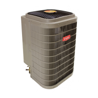
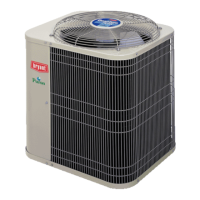
Fig. 1 – Piping Installation
When outdoor unit is connected to factory–approved indoor unit,
outdoor unit contains system refrigerant charge for operation with AHRI
rated indoor unit when connected by 15 ft. (4.57 m) of field–supplied or
factory accessory tubing.
For proper unit operation, check refrigerant charge using charging
information located on control box cover and/or in the Check Charge
section of this instruction.
IMPORTANT: Maximum liquid-line size is 3/8-in. OD for all
residential applications including long line. Refer to Residential Piping
and Longline Guideline for further information.
IMPORTANT: Always install the factory-supplied liquid-line filter
drier. If replacing the filter drier, refer to Product Replacement Parts List.
for appropriate part number. Obtain replacement filter driers from your
distributor or branch.
Installation
IMPORTANT: Effective January 1, 2015, all split system and packaged
air conditioners must be installed pursuant to applicable regional
efficiency standards issued by the Department of Energy.
Check Equipment and Job Site
UNPACK UNIT
Move to final location. Remove carton taking care not to damage unit.
Inspect Equipment
File claim with shipping company prior to installation if shipment is
damaged or incomplete. Locate unit rating plate on unit corner panel. It
contains information needed to properly install unit. Check rating plate
to be sure unit matches job specifications.
Install on a Solid, Level Mounting Pad
If conditions or local codes require the unit be attached to pad, tie down
bolts should be used and fastened through knockouts provided in unit
base pan. Refer to unit mounting pattern in Fig. 2 to determine base pan
size and knockout hole location.
For hurricane tie downs, contact local distributor for details and PE
(Professional Engineer) certification, if required.
On rooftop applications, mount on level platform or frame. Place unit
above a load-bearing wall and isolate unit and tubing set from structure.
Arrange supporting members to adequately support unit and minimize
transmission of vibration to building. Consult local codes governing
rooftop applications.
Roof mounted units exposed to winds may require wind baffles. Consult
the Application Guideline and Service Manual - Residential Split
System Air Conditioners and Heat Pumps for wind baffle construction.
NOTE: Unit must be level to within ±2_ (±3/8 in./ft ,.±9.5 mm/m) per
compressor manufacturer specifications.
Clearance Requirements
When installing, allow sufficient space for airflow clearance, wiring,
refrigerant piping, and service. Allow 24 in. (609.6 mm) clearance to
service end of unit and 48 in. (1219.2 mm) (above unit. For proper
airflow, a 6-in. (152.4 mm) clearance on 1 side of unit and 12-in. (304.8
mm) on all remaining sides must be maintained. Maintain a distance of
24 in. (609.6 mm) between units or 18 in. (457.2 mm) if no overhang
within 12 ft. (3.66 m) Position so water, snow, or ice from roof or eaves
cannot fall directly on unit.
NOTE: 18” (457.2 mm) clearance option described above is approved
for outdoor units with wire grille coil guard only. Units with louver
panels require 24” (609.6 mm) between units.
On rooftop applications, locate unit at least 6 in. (152.4 mm) above roof
surface.
Operating Ambient
The minimum outdoor operating ambient in cooling mode without
accessory is 55°F (13°C).
Make Piping Connections
CAUTION
!
CUT HAZARD
Failure to follow this caution may result in personal injury.
Sheet metal parts may have sharp edges or burrs. Use care and wear
appropriate protective clothing and gloves when handling parts.
INSULATION
SUCTION TUBE
LIQUID TUBE
OUTDOOR WALL INDOOR WALL
LIQUID TUBE
SUCTION TUBE
INSULATION
CAULK
HANGER STRAP
(AROUND SUCTION
TUBE ONLY)
JOIST
1” (25.4 mm)
MIN
THROUGH THE WALL
SUSPENSION
WARNING
!
PERSONAL INJURY AND ENVIRONMENTAL
HAZARD
Failure to follow this warning could result in personal injury or death.
Relieve pressure and recover all refrigerant before system repair or
final unit disposal. Use all service ports and open all flow-control
devices, including solenoid valves.
Federal regulations require that you do not vent refrigerant to the
atmosphere. Recover during system repair or final unit disposal.
CAUTION
!
UNIT DAMAGE HAZARD
Failure to follow this caution may result in equipment damage or
improper operation.
If ANY refrigerant tubing is buried, provide a 6-in (152.4 mm). vertical
rise at service valve. Refrigerant tubing lengths up to 36-in (914.4
mm). may be buried without further special consideration. Do not bury
lines more than 36-in. (914.4 mm).
 Loading...