126S: Installation Instructions
Manufacturer reserves the right to change, at any time, specifications and designs without notice and without obligations.
3
A05177
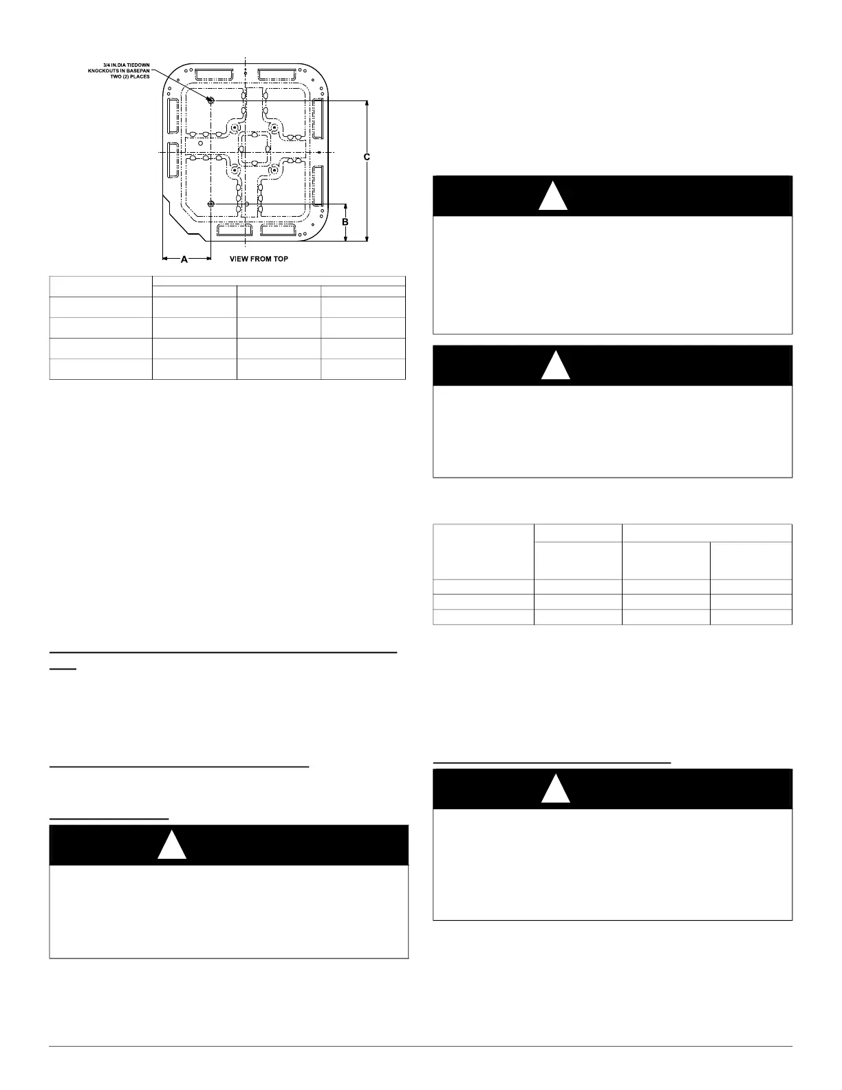
Fig. 2 – Tiedown Knockout Locations
Outdoor units may be connected to indoor section using accessory
tubing package or field-supplied refrigerant grade tubing of correct size
and condition. Rated tubing diameters shown in Table 1 are
recommended up to 80 ft. (24.38 m). See Product Data for acceptable
alternate vapor diameters and associated capacity losses. For tubing
requirements beyond 80 ft. (24.38 m), substantial capacity and
performance losses can occur. Following the recommendations in the
Residential Piping and Long Line Guideline will reduce these losses.
Refer to Table 1 for field tubing diameters. Refer to Table 6 for
accessory requirements.
There are no buried-line applications greater than 36-in. (914.4 mm)
allowed.
If refrigerant tubes or indoor coil are exposed to atmosphere, they must
be evacuated to 500 microns to eliminate contamination and moisture in
the system.
Outdoor Unit Connected to Factory Approved Indoor
Unit
Outdoor unit contains approximate system refrigerant charge for
operation with factory approved AHRI rated indoor unit when connected
by 15 ft. (4.57 m) of field-supplied or factory-accessory tubing, and
factory supplied filter drier. Check refrigerant charge for maximum
efficiency.
Refrigerant Tubing Connection Outdoor
Connect vapor and liquid tubes to fittings on vapor and liquid service
valves (see Table 1.) Use refrigerant grade tubing
Sweat Connection
Use refrigeration grade tubing. Service valves are closed from factory
and ready for brazing. Clean line set tube ends with emery cloth or steel
brush. Remove any grit or debris. Insert line set tube ends into service
valve tube stubs. Apply heat absorbing paste or heat sink product
between service valve and joint. Wrap service valves with a heat sinking
material such as a wet cloth. Braze joints using a Sil--Fos or
Phos--copper alloy. Consult local code requirements.
Refrigerant tubing and indoor coil are now ready for leak testing. This
check should include all field and factory joints.
NOTE: Some outdoor units contain a mechanical fitting at the liquid
distributor. This connection is not field serviceable and should not be
disturbed.
Notes:
1. Do not apply capillary tube to these units.
2. For Tubing Set lengths between 80 and 200 ft. (26.7 and 61.0 m) horizontal or 35 ft.
(10.7 m) vertical differential 250 ft. (76.2 m) Total Equivalent Length), refer to the
Residential Piping and Longline Guideline- Air Conditioners and Heat Pumps using
Puron refrigerant.
3. For alternate liquid line options on 18-42 size units, see Product Data or Residential
Piping and Application Guideline
Install Liquid-Line Filter Drier Indoor
UNIT BASE PAN
Dimension in. (mm)
TIEDOWN KNOCKOUT LOCATIONS in. (mm)
A B C
23-1/2 X 23-1/2
(596.9 X 596.9)
7-13/16 (198.4) 4–7/16 (112.7) 18–1/16 (458.8)
26 X 26
(660.4 X 660.4)
9–1/8 (231.8) 4–7/16 (112.7) 21–1/4 (539.8)
31–1/2 X 31–1/2
(800.1 X 800.1)
9–1/8 (231.8) 6–9/16 (166.7) 24–11/16 (627.1)
35 X 35
(889 X 889)
9–1/8 (231.8) 6–9/16 (166.7) 28–7/16 (722.3)
CAUTION
!
UNIT DAMAGE HAZARD
Failure to follow this caution may result in equipment damage or
improper operation.
Service valves must be wrapped in a heat-sinking material such as a wet
cloth while brazing.
WARNING
!
FIRE HAZARD
Failure to following this warning could result in personal injury, death
and/or property damage.
Refrigerant and oil mixture could ignite and burn as it escapes and
contacts brazing torch. Make sure the refrigerant charge is properly
removed from both the high and low sides of the system before brazing
any component or lines.
CAUTION
!
BURN HAZARD
Failure to follow this caution may result in personal injury
Components will be HOT after brazing. Wear appropriate personal
protective equipment and allow to cool before handling parts and
equipment.
Table 1 – Refrigerant Connections and Recommended Liquid and
Vapor Tube Diameters (In.)
UNIT SIZE
LIQUID
*
RATED VAPOR
*
*. Units are rated with 25 ft. (7.6 m) of lineset. See Product Data sheet for
performance data when using different size and length linesets.
Connection
& Max. Tube
Diameter
Connection
Diameter
Tube
Diameter
18, 24, 30 3/8 3/4 3/4
36, 42, 48, 49 3/8 7/8 7/8
60, 61 3/8 7/8 1-1/8
CAUTION
!
UNIT DAMAGE HAZARD
Failure to follow this caution may result in equipment damage or
improper operation.
1. Installation of filter drier in liquid line is required.
2. Filter drier must be wrapped in a heat-sinking material such as a wet
cloth while brazing.
 Loading...