126S: Installation Instructions
Manufacturer reserves the right to change, at any time, specifications and designs without notice and without obligations.
10
A02326A/A97368
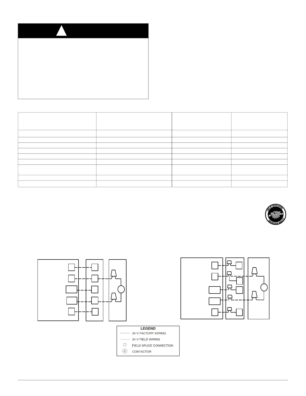
Fig. 8 – Generic Wiring Diagrams (See Thermostat Installation Instruction for specific unit combinations)
WARNING
!
PERSONAL INJURY AND/OR PROPERTY DAMAGE
HAZARD
Failure to follow this warning could result in personal injury and/or
property damage.
For continued performance, reliability, and safety, the only approved
accessories and replacement parts are those specified by the equipment
manufacturer. The use of non-manufacturer approved parts and
accessories could invalidate the equipment limited warranty and result
in fire risk, equipment malfunction, and failure.
Please review manufacturer's instructions and replacement part catalogs
available from your equipment supplier.
Table 6 – Accessory Usage
ACCESSORY
REQUIRED FOR LOW-AMBIENT COOLING
APPLICATIONS
(Below 55F/13°C)
REQUIRED FOR LONG LINE
APPLICATIONS
*
*.For tubing line sets between 80 and 200 ft. (26.7 and 60.96 m) and/or 35 ft. (10.7 m) vertical differential, refer to Residential Piping and Longline Guideline.
REQUIRED FOR
SEA COAST
APPLICATIONS
(Within 2 miles/3.22 km)
Ball Bearing Fan Motor
Yes
†
†.Additional requirement for Low-Ambient Controller (full modulation feature) MotorMaster® Control.
No No
Compressor Start Assist Capacitor and Relay Yes Yes No
Crankcase Heater Yes Yes No
Evaporator Freeze Thermostat Yes No No
Hard Shut-Off TXV Yes Yes No
Liquid Line Solenoid Valve No No No
Motor Master
or Low-ambient Pressure
Switch
Yes No No
Support Feet Recommended No Recommended
Winter Start Control
Yes
‡
‡.Required if Low Pressure Switch is factory or field installed.
No No
24 VAC HOT
24 VAC COM
R
C
G
W/W1
Y/Y2
R
C
C
A/C
THERMOSTAT
Typical
FAN COIL
AIR
CONDITIONER
G
W2
HEAT STAGE 1
COOL STAGE 1
INDOOR FAN
24 VAC HOT
24 VAC COM
R
C
G
W/W1
Y/Y2
R
C
C
A/C
THERMOSTAT
Typical
FURNACE
AIR
CONDITIONER
Y
G
W
HEAT STAGE 1
COOL STAGE 1
INDOOR FAN