4
LONG LINE APPLICATIONS
An application is considered Long Line, when the refrigerant level in the system requires the use of accessories to maintain acceptable
refrigerant management for systems reliability. See Accessory Usage Guideline table for required accessories. Defining a system as long line
depends on the liquid line diameter, actual length of the tubing, and vertical separation between the indoor and outdoor units.
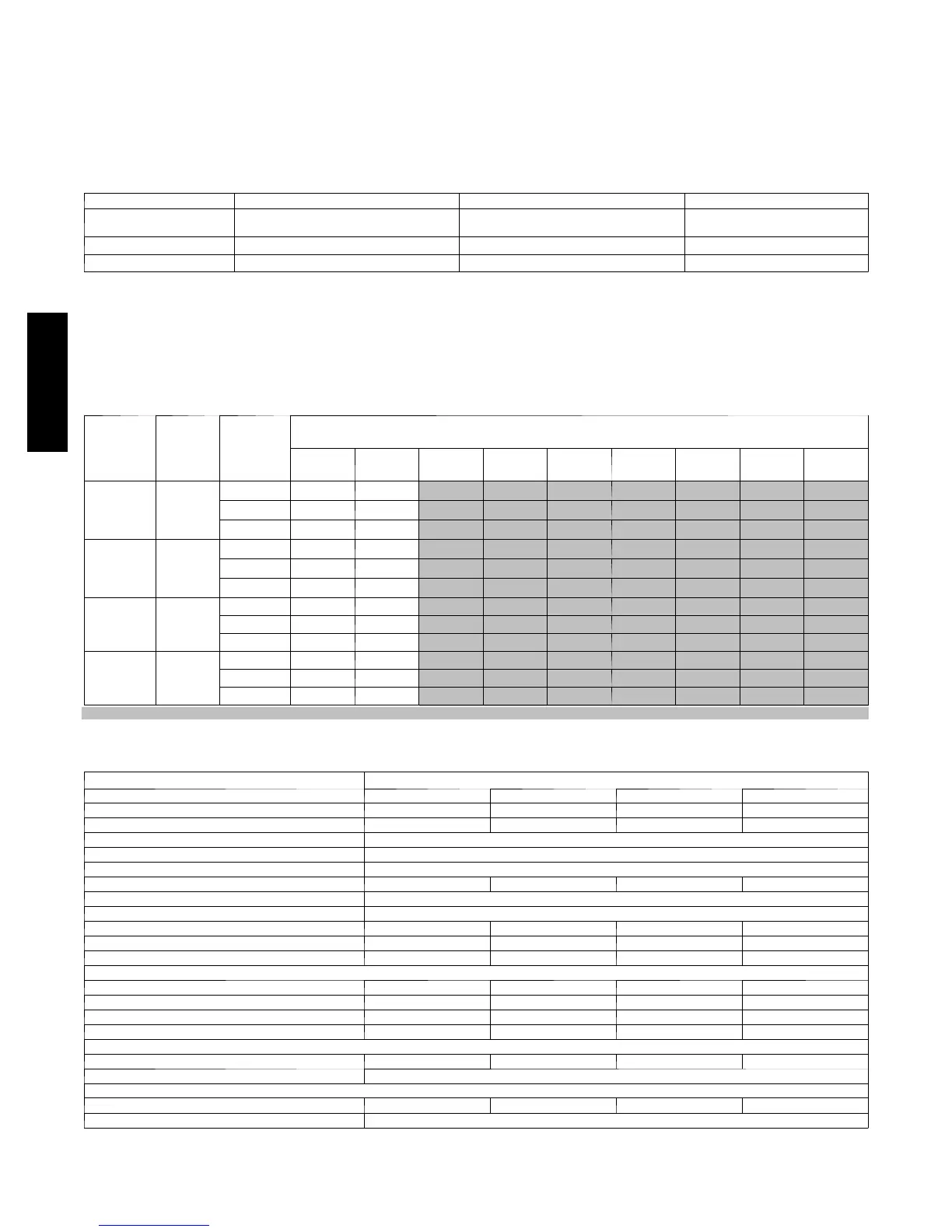
For Air Conditioner systems, the chart below shows when an application is considered Long Line.
AC WITH PURONr REFRIGERANT LONG LINE DESCRIPTION ft (m)
Beyond these lengths, long line accessories are required
Liquid Line Size Units On Same Level Outdoor Below Indoor Outdoor Above Indoor
1/4
No accessories needed within al lowed
lengths
No accessories needed within al lowed
lengths
175 (53.3)
5/16 120 (36.6) 50 (15.2) vertical or 120 (36.6) total 120 (36.6)
3/8 80 (24.4) 35 (10.7) vertical or 80 24.4) total 80 (24.4)
Note: SeeLongLineGuidelinefordetails
VAPOR LINE SIZING AND COOLING CAPACITY LOSS
Acceptable vapor line diameters provide adequate oil return to the compressor while avoiding excessive capacity loss. The suction line
diameters shown in the chart below are acceptable for AC systems with Puron refrigerant:
Vapor Line Sizing and Cooling Capacity Losses — Puronr Refrigerant 2--Stage Air Conditioner Applications
Unit
Nominal
Size (Btuh)
Maximum
Liquid
Line
Diameters
(In. OD)
Vapor Line
Diameters
(In.) OD
Cooling Capacity Loss (%)
Total Equivalent Line Le ngth ft. (m)
26--- 50
(7.9--- 15.2)
51--- 80
(15.5--- 24.4)
81--- 100
(24.7--- 30.5)
101--- 125
(30.8--- 38.1)
126--- 150
(38.4--- 45.7)
151--- 175
(46.0--- 50.3)
176--- 200
(53.6--- 60.0)
201--- 225
(61.3--- 68.6)
226--- 250
(68.9--- 76.2)
024
2 --- S t a g e
Puron
AC
3/8
5/8 0 1 1 2 3 3 4 4 5
3/4 0 0 0 0 1 1 1 1 1
7/8 0 0 0 0 1 1 1 1 1
036
2 --- S t a g e
Puron
AC
3/8
5/8 1 2 4 5 6 7 9 10 11
3/4 0 0 1 1 2 2 3 3 4
7/8 0 0 0 0 1 1 1 1 2
048
2 --- S t a g e
Puron
AC
3/8
3/4 1 2 2 3 4 5 6 7 7
7/8 0 1 1 2 2 2 3 3 3
1 --- 1 / 8 0 0 — — — — — — —
060
2 --- S t a g e
Puron
AC
3/8
3/4 1 2 4 5 6 7 9 10 11
7/8 0 1 2 2 3 4 4 5 5
1 --- 1 / 8 0 0 0 1 1 1 1 1 1
Applications in this area may be long line and may have height restrictions. See the Residential Piping and Long Line Guideline.
— Applications in this area are not recommended due to insufficient oil return
PHYSICAL DATA
Model 180BNA
Unit Size --- Series 024--- A 036--- B 048--- A 060--- A
Operating Weight lb (kg) 323 (147) 324 (147) 325 (147) 350 (159)
Shipping Weight lb (kg) 368 (167) 368 (167) 370 (168) 394 (179)
Compressor Ty pe 2 --- S t ag e S c ro l l
REFRIGERANT Puronr ( R ---410A)
Control TXV (Puronr Hard Shutoff)
Charge lb (kg) 14.21 (6.67) 14.36 (6.51) 14.45 ( 6.55) 14.83 (6.73)
COND FAN Propeller Type, Direct Drive
Air Discharge Vertical
Air Qty (CFM) 3000 / 3637 3124 / 3700 3703 / 4304 4209 / 4668
Motor HP 1/5 1/5 1/5 1/5
Motor RPM 628 / 752 582 / 669 659 / 765 742 / 828
COND COIL
Face Area (Sq ft) 30.18 30.18 30.18 30.18
Fins per In. 20 20 20 20
Rows 2 2 2 2
Circu its 9 9 9 9
VALVECONNECT.(In.ID)
Vapor 7/8 7/8 7/8 7/ 8
Liquid 3/8
REFRIGERANT TUBES (In. OD)
Rated Vapor* 7/8 7/8 1 --- 1 /8 1 --- 1 / 8
Liquid 3/8
*Units are rated with 25 ft (7.6 m) of lineset length. See Vapor Line Sizing and Cooling Capacity Loss table when using other sizes and lengths of lineset.
180B