4. Set room thermostat at desired temperature. Be sure set
point is below indoor ambient temperature.
5. Set room thermostat to COOL and fan control to ON or
AUTO mode, as desired. Operate unit for 15 minutes.
Check system refrigerant charge.
A. SEQUENCE OF OPERATION
Turn on power to indoor and outdoor units. Transformer is
energized.
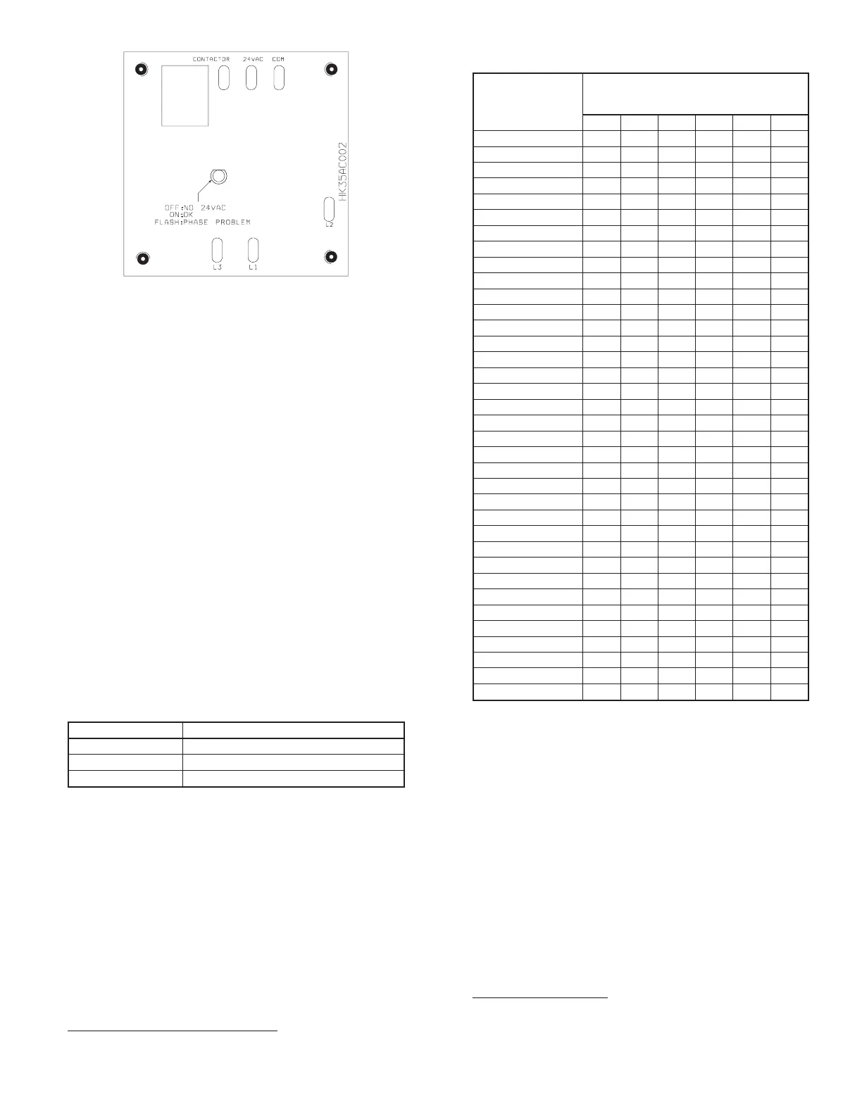
On a call for cooling, thermostat makes circuits R-Y and R-G. On
three phase models with scroll compressors, the units are equipped
with a phase monitor to detect in the incoming power is correctly
phased for compressor operation. If the phasing is correct, circuit
R-Y energizes contactor, starting outdoor fan motor and compres-
sor circuit. R-G energizes indoor unit blower relay, starting indoor
blower motor on high speed.
NOTE: If the phasing is incorrect, the contactor will not be
energized. To correct the phasing, interchange any two of the three
power connections on the field side.
When thermostat is satisfied, its contacts open, de-energizing
contactor and blower relay. Compressor and motors stop.
If indoor unit is equipped with a time-delay relay circuit, the
indoor blower runs an additional 90 sec to increase system
efficiency.
XII. CHECK CHARGE
A. Unit Charge
Factory charge and charging method are shown on unit informa-
tion plate. Charge Puron® units using a commercial-type metering
device in manifold hose. Charge refrigerant into suction line.
NOTE: If superheat or subcooling charging conditions are not
favorable, charge must be weighed in accordance with unit rating
plate ± 0.6 oz/ft of 3/8-in. liquid line above or below 15 ft
respectively.
EXAMPLE:
25 ft - 15 ft = 10 ft X 0.6 oz/ft=6ozofadditional charge
B. Cooling Only Procedure
Units With Cooling Mode Puron® TXV
Units installed with cooling mode TXV require charging by the
subcooling method.
1. Operate unit a minimum of 10 minutes before checking
charge.
2. Measure liquid service valve pressure by attaching an
accurate gage to service port.
3. Measure liquid line temperature by attaching an accurate
thermistor type or electronic thermometer to liquid near
outdoor coil.
4. Refer to unit rating plate for required subcooling tempera-
ture.
5. Refer to Table 4. Find the point where required subcooling
temperature intersects measured liquid service valve pres-
sure.
6. To obtain required subcooling temperature at a specific
liquid line pressure, add refrigerant if liquid line tempera-
ture is higher than indicated or reclaim refrigerant if
temperature is lower. Allow a tolerance of ± 3°F.
Units With Indoor Pistons
Units installed with indoor pistons require charging by the super-
heat method.
The following procedure is valid when indoor airflow is within ±
21 percent of its rated CFM.
Fig. 10—Phase Monitor Control
A00010
TABLE 3—PHASE MONITOR LED INDICATORS
LED STATUS
OFF No call for compressor operation
FLASHING Reversed phase
ON Normal
TABLE 4—REQUIRED LIQUID-LINE TEMPERATURE (°F)
LIQUID
PRESSURE AT
SERVICE VALVE
(PSIG)
REQUIRED SUBCOOLING
TEMPERATURE
(°F)
8 1012141618
189 58 56 54 52 50 48
195 60 58 56 54 52 50
202 62 60 58 56 54 52
208 64 62 60 58 56 54
215 66 64 62 60 58 56
222 68 66 64 62 60 58
229 70 68 66 64 62 60
236 72 70 68 66 64 62
243 74 72 70 68 66 64
251 76 74 72 70 68 66
259 78 76 74 72 70 68
266 80 78 76 74 72 70
274 82 80 78 76 74 72
283 84 82 80 78 76 74
291 86 84 82 80 78 76
299 88 86 84 82 80 78
308 90 88 86 84 82 80
317 92 90 88 86 84 82
326 94 92 90 88 86 84
335 96 94 92 90 88 86
345 98 96 94 92 90 88
354 100 98 96 94 92 90
364 102 100 98 96 94 92
374 104 102 100 98 96 94
384 106 104 102 100 98 96
395 108 106 104 102 100 98
406 110 108 106 104 102 100
416 112 110 108 106 104 102
427 114 112 110 108 106 104
439 116 114 112 110 108 106
450 118 116 114 112 110 108
462 120 118 116 114 112 110
474 122 120 118 116 114 112
486 124 122 120 118 116 114
499 126 124 122 120 118 116
511 128 126 124 122 120 118
—7—
 Loading...