NOTE TO INSTALLER:
This manual should be left with the equipment owner.
FOR YOUR SAFETY
Do not store or use gasoline or other flammable
vapor and liquids in the vicinity of this or any other
appliance.
WARNING:Improper installation, adjustment, alter-
ation, service, or maintenance can cause injury or
property damage. Refer to this manual. For assistance
or additional information, consult a qualified installer,
service agency, or the gas supplier.
FOR YOUR SAFETY
WHAT TO DO IF YOU SMELL GAS
•
Do not try to light any appliance.
• Do not touch any electrical switch; do not use any phone
in your building.
• Immediately call your gas supplier from a neighbor’s
phone. Follow the gas supplier’s instructions.
• If you cannot reach your gas supplier, call the fire
department.
WARNING:Before performing recommended main-
tenance, be sure main power switch to unit is turned
off. Electrical shock could cause personal injury.
Your combination heating/cooling unit is equipped with an
automatic intermittent pilot and induced draft power com-
bustion blower.
WARNING:
Pilot will light automatically. Do not at-
tempt to light by hand; explosion and personal injury
may result.
TO LIGHT UNIT
DANGER:
1. Do not turn off the electrical power to unit with-
out first turning off the gas supply.
2. Before attempting to start the gas heating sec-
tion, familiarize yourself with all the procedures
that must be followed.
3. Never attempt to manually light the pilot on unit
with a match, lighter, or any other flame. If the
electric sparking device fails to light the pilot, re-
fer to the shutdown procedures, then call your dealer
as soon as possible.
If you do not follow these instructions exactly, a fire or
explosion may result, causing property damage, injury,
or loss of life.
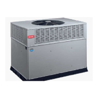
See Fig. 1 for location of gas valves. Refer to Fig. 2 while pro-
ceeding with the following steps.
Step 1
Set room thermostat to the lowest temperature setting and
set SYSTEM switch to HEAT position.
Step 2
Close the external manual gas valve.
Step 3
Turn off the electrical supply to the unit.
Step 4
Remove the burner compartment access panel.
Step 5
Turn the control dial on the internal gas valve counterclock-
wise to the OFF position and wait 5 minutes.
Step 6
Turn control dial on internal gas valve clockwise to
ON position.
Step 7
Replace the burner compartment access panel.
Step 8
Turn on the electrical supply to unit.
Step 9
Open the external gas valve.
INTEGRATED GAS
UNIT CONTROLLER
(HIDDEN)
INDUCED DRAFT
MOTOR
FLUE BOX
COVER
MAIN BURNER
SECTION
MAIN GAS
VALVE
COMBUSTION
FAN HOUSING
Fig.1—Typical Gas Heating Section
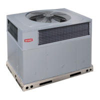
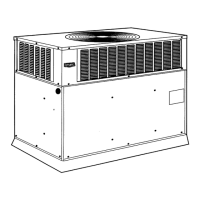
user’s information manual
SINGLE PACKAGE ROOFTOP GAS
HEATING/ELECTRIC COOLING UNITS
579F
581A
Sizes 155-300
(13 to 25 Tons)
Cancels: OM11-10 OM11-15
9/15/96