CONTENTS
Page
SAFETY CONSIDERATIONS ........................1
GENERAL ......................................1-3
RECEIVING AND INSTALLATION .................4-14
I. Step 1 — Check Equipment ..................4
II. Step 2 — Provide Unit Support ...............4
III. Step 3 — Field Fabricate Ductwork ............4
IV. Step 4 — Provide Clearances .................4
V. Step 5 — Rig and Place Unit .................4
VI. Step 6 — Connect Condensate Drain ..........7
VII. Step 7 — Install Flue Hood ...................7
VIII. Step 8 — Install Gas Piping ..................7
IX. Step 9 — Install Duct Connections ...........10
X. Step 10 — Install Electrical Connections ......11
PRE-START-UP ................................14,15
START-UP ....................................15-29
I. Check for Refrigerant Leaks .................15
II. Start Up Heating Section and
Make Adjustments .........................15
III. Start Up Cooling Section and
Make Adjustments .........................18
MAINTENANCE ................................29-32
I. Air Filter ..................................30
II. Evaporator Blower and Motor ................30
III. Flue Gas Passageways .....................30
IV. Combustion-Air Blower .....................30
V. Limit Switch ..............................30
VI. Burner Ignition ............................31
VII. Main Burners .............................31
VIII. Condenser Coil, Evaporator Coil, and
Condenser Drain Pan .......................31
IX. Condenser Fan ............................32
X. Electrical Controls and Wiring ...............32
XI. Refrigerant Circuit .........................32
XII. Gas Input .................................32
XIII. Evaporator Airflow .........................32
XIV. Metering Device — Acutrol™ Device ..........32
XV. Liquid Line Strainer ........................32
TROUBLESHOOTING ...........................33-35
START-UP CHECKLIST ..........................CL-1
NOTE TO INSTALLER — Beforetheinstallation,READTHESE
INSTRUCTIONS CAREFULLY AND COMPLETELY. Also,
make sure the User’s Manual and Replacement Guide are
left with the unit after installation. The furnace is NOT to be
used for temporary heating of buildings or structures under
construction.
SAFETY CONSIDERATIONS
Installation and servicing of air-conditioning equipment can
be hazardous due to system pressure and electrical compo-
nents. Only trained and qualified personnel should install,
repair, or service air-conditioning equipment.
Untrained personnel can perform basic maintenance func-
tions of cleaning coils and filters. All other operations should
be performed by trained service personnel. When working on
air-conditioning equipment, observe precautions in the lit-
erature, tags and labels attached to the unit, and other safety
precautions that may apply.
Follow all safety codes. Wear safety glasses and work gloves.
Use quenching cloth for unbrazing operations. Have fire ex-
tinguisher available for all brazing operations.
WARNING:
Improper installation, adjustment, alter-
ation, service, maintenance, or use can cause carbon mon-
oxide poisoning, fire, or an explosion which can result
in personal injury or unit damage. Consult a qualified
installer, service agency, or gas supplier for informa-
tion or assistance. The qualified installer or agency must
use only factory-authorized kits or accessories when modi-
fying this product.
WARNING:
Before performing service or mainte-
nance operations on unit, turn off gas supply then unit
main power switch. Electrical shock could cause per-
sonal injury.
GENERAL
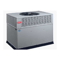
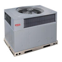
The 582A and 583A units (see Fig. 1) are fully self-contained,
combination Category I gas heating/electric cooling units de-
signed for outdoor installation. See Fig. 2 and 3 (pages 2,3)
for unit dimensions. All unit sizes have return and discharge
openings for both horizontal and downflow configurations, and
are factory shipped with all downflow duct openings covered.
Units may be installed on a rooftop, a cement slab, or di-
rectly on the ground (if permitted by local codes). See Fig. 4
for roof curb dimensions.
Fig. 1 — Units 582A and 583A
(Shown with Accessory Wire Grille)
installation, start-up
and service instructions
SINGLE PACKAGE GAS HEATING/
ELECTRIC COOLING UNITS
582A
Sizes 018-060
583A
Sizes 024-060
1
1
⁄
2
to 5 Nominal Tons
Cancels: II 582A-18-1 II 582A-18-2
3/15/99