SAFETY CONSIDERATIONS
Installing and servicing air-conditioning equipment can be haz-
ardous due to system pressure and electricalcomponents. Only
trained and qualified service personnel should install or serv-
ice air-conditioning equipment.
Recognize safety information. This is the safety-alert symbol
( ). When you see this symbol on the unit and in instruc-
tions or manuals, be alert to the potential for personal
injury.
Understand the signal words — DANGER, WARNING, and
CAUTION. These words are used with the safety-alert sym-
bol. Danger identifies the most serious hazards which will
result in severe personal injury or death. Warning indicates
a situation that could result in personal injury. Caution is
used to identify unsafe practices which would result in minor
personal injury or product and property damage.
Untrained personnel can perform basic maintenance, such as
cleaning and replacing filters. All other operations should be
performed by trained service personnel. When working on air-
conditioning equipment, observe safety precautions in litera-
ture, and tags and labels attached to unit.
Follow all safety codes. Wear safety glasses and work gloves.
Use quenching cloth for brazing operations. Have fire extin-
guisher available. Read these instructions thoroughly. Con-
sult local building codes and National Electrical Code (NEC)
Standard ANSI/NFPA 70 (American National Standards
Institute/National Fire Protection Association) for special in-
stallation requirements.
WARNING:
Before installing or servicing system, al-
ways turn off main power to system. There may be more
than one disconnect switch, since each fan coil unit will
normally have its own disconnect. Turn off accessory
heater power if applicable. Electrical shock can cause
personal injury.
GENERAL
IMPORTANT: Before installing a multi-split system, care-
fully read the following information:
• The TXV (thermostatic expansion valve) is located in the
outdoor unit, NOT the indoor fan coil units.
• The 538S outdoor unit has a factory-installed low-ambient
control which permits unit operation down to 0° F outdoor
ambient temperatures.
• BOTHrefrigerant lines between the indoor and outdoor units
MUST BE insulated, because the TXV is in the outdoor
unit.
• If the installation includes a 619C ceiling-suspended fan
coil unit, REMOVE the AccuRatert device.
• DO NOT install a filter drier in the line set to the fan coil
units. A filter drier has already been factory-installed on
the outdoor unit.
• DO NOT run thermistor wires and control wires in the same
jacket.
• The 538S unit has been pre-charged at the factory with
sufficient refrigerant for the entire system (assuming 25 ft
of tubing and the use of one of the system combinations
listed in Planning the System section on this page).
I. SYSTEM DESCRIPTION
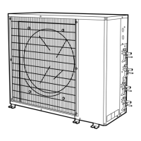
The 538S multi-split air conditioning system requires 3 ma-
jor components (see Fig. 1):
• A 538S outdoor condensing unit
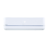
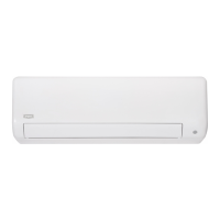
• Either 2, 3, or 4 duct-free split fan coil units for distribu-
tion of air to a maximum of 4 independent zones (see Plan-
ning the System section on this page)
• A wired or wireless infrared remote controller to control
each fan coil unit independently (one remote controller is
necessary for each fan coil unit)
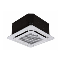
NOTE: The remote controller is not available for 619F in-
ceiling cassette fan coil units.
IMPORTANT: The 538S outdoor units may only be used with
the indoor fan coil unit sizes listed in Planning the System
section below. DO NOT try to substitute or add more fan
coils to these systems.
II. PLANNING THE SYSTEM
This is a complex system with up to 4 separate tubing sys-
tems and 8 different control cable sets. Plan the installation
carefully as instructed below. Read these installation instruc-
tions (outdoor condensing unit) and the installation instruc-
tions included with each fan coil unit carefully and completely
PRIOR to system installation.
1. Maximum line length is 50 ft equivalent (any single line
run), and maximum elevation differential is 30 ft (from
highest to lowest system component).
2. Verify that components received form a legitimate multi-
split system as follows:
a. Systems using one 538S
_
024 outdoor condensing unit
may use any combination (for a system total of 2 fan
coil units) of nominal 1
1
⁄
2
ton fan coil units.
b. Systems using one 538S
_
048 outdoor condensing unit
may use any of the following combinations:
• any combination (for a total of 2 fan coil units) of
nominal 2 ton fan coil units (1 fan coil unit per
circuit).
• any one nominal 2-ton fan coil unit on one circuit,
and any combination of 2 nominal 1
1
⁄
2
ton fan coil
units (for a system total of 3 fan coil units) on the
other circuit.
• any combination (for a system total of 4 fan coil
units) of nominal 1
1
⁄
2
ton fan coil units (2 fan coil
units per circuit).
3. Identify and record each fan coil section as it will be con-
nected to the 538S outdoor unit on the Multi-Split
Installation Planning Worksheet included as part of the
Start-Up Checklist on page CL-1.
4. Check all system components to ensure that all re-
quired materials are on hand before starting installa-
tion of this system.
5. Re-read Installation section Step III — Install Fan Coil
Units, on page 4 before installing indoor fan coil units.
INSTALLATION
I. COMPLETE PRE-INSTALLATION CHECKS
A. Unpack Outdoor Unit (see Fig. 1)
Move 538S unit to final location. Remove carton from unit,
being careful not to damage service valves and grilles.
B. Inspect Shipment
File claim with shipping company if shipment is damaged or
incomplete. Check unit nameplate to be sure unit matches
job requirements.
C. Consider System Requirements
Consult local building codes and NEC for special installation
requirements.
Allow sufficient space for airflow, wiring, refrigerant piping,
and servicing unit. See Fig. 2 and 3.
Locate unit so that condenser coil airflow is unrestricted on
both sides. Refer to Fig. 2 and 3.
—2—
 Loading...