Do you have a question about the Bryant 619PEQ018BBMA and is the answer not in the manual?
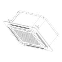
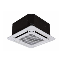
Steps and guidance for installing the indoor unit.
Instructions on creating holes for pipes and wiring.
Visual guides for electrical connections.
Details on the location of the terminal block.
Instructions for connecting and insulating the drain line.
Performing a test run to verify functionality.
Checks related to the indoor unit's functions.
Error code display and LED status for indoor unit diagnostics.
This document provides installation and operational instructions for the Bryant 619PB High Wall Ductless System, available in sizes ranging from 09 to 36. This system is designed for air conditioning and heating applications, offering a compact and efficient solution for various indoor environments.
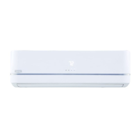
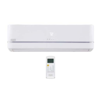
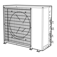
The system's primary function is to provide heating and cooling, ensuring comfortable indoor temperatures. It operates as a heat pump, capable of both cooling and heating modes. The indoor unit is typically mounted on a wall, designed to blend with interior aesthetics while delivering effective air distribution.
Installation of the 619PB system requires careful attention to safety and adherence to local codes. The manual emphasizes that only trained and qualified installers and service mechanics should perform the installation, start-up, and servicing of this equipment due to potential hazards related to system pressures, electrical components, and equipment location.
Key installation steps include:
The 619PB system offers flexible control options:
Regular maintenance is crucial for the longevity and efficient operation of the 619PB system. The manual outlines several key maintenance-related features and instructions:
The 619PB system is designed with user convenience and serviceability in mind, providing clear instructions for installation, operation, and troubleshooting to ensure reliable performance.
| Brand | Bryant |
|---|---|
| Model Number | 619PEQ018BBMA |
| Category | Air Conditioner |
| Refrigerant | R-410A |
| Operating Voltage | 208/230V |
| Phase | 1 |
| Cooling Capacity | 18, 000 BTU |
| Unit Dimensions (Outdoor) | 31.5 x 31.5 x 26.5 inches |