10
INSTALLATION TIPS
Ideal installation locations include:
Indoor Unit
S A location where there are no obstacles near the inlet and outlet
area.
S A location which can bear the weight of the indoor unit.
S Do not install the indoor units near a direct source of heat such as
direct sunlight or a heating appliance.
S A location which provides appropriate clearances (see Fig. 6.)
INDOOR UNIT INSTALLATION
PRIOR TO INSTALLATION
Before installing the indoor unit, ensure the compatibility with the
outdoor unit using the product data as a reference.
Select the Installation Location:
Before installing the indoor unit, choose an appropriate location.
The following are standards that should help you choose an
appropriate location for the unit. Proper installation locations must
meet the following standards:
1. Good air circulation
2. Convenient drainage
3. Noise from the unit will not disturb others
4. Firm and solid—the location will not vibrate
5. A site strong enough to support the unit’s weight
6. A location at least 3.28 ft. (1m) from all other electrical
devices (e.g., TV, radio, computer)
7. DO NOT install the unit in the following locations:
a. Near any source of heat, steam, or combustible gas
b. Near flammable items such as curtains or clothing
c. Near any obstacle that might block air circulation
d. Near the doorway
e. In a location subject to direct sunlight
NOTE: Wall Holes (if there is no fixed refrigerant piping)
While choosing a location, leave ample room for a wall hole (refer
to the Drill Hole in Wall for the Interconnecting Piping, Drain and
Wiring section for connective piping step) for the signal cable and
the refrigerant piping that connect the indoor and outdoor units.
The default position for all piping is the right side of the indoor
unit (while facing the unit). However, the unit can accommodate
piping to both the left and right sides.
Attach the Mounting Plate to the Wall:
1. Carefully remove the mounting plate, which is attached to
the back of the indoor unit.
2. Using the Stencil, determine the wall hole position. The
mounting plate should be located horizontally and level on
the wall. All minimum spacings shown in Fig. 6 should be
maintained.
3. If the wall is block, brick, concrete or similar material, drill
0.2” (5 mm) diameter holes and insert the anchors for the
appropriate mounting screws.
4. Attach the mounting plate to the wall.
Mounting Plate Dimensions
Different model sizes have different mounting plates. Ensure
there’s enough room to mount the indoor unit (refer to Fig. 6). The
following measurements can be located on these figures:
S Width of mounting plate
S Height of mounting plate
S Width of indoor unit relative to plate
S Height of indoor unit relative to plate
S Recommended position of wall hole (both to the left and
right of mounting plate)
S Relative distances between the screw holes.
Correct orientation of Mounting Plate
Fig. 7 - Mounting Plate Orientation
DRILL HOLE IN WALL FOR THE
INTERCONNECTING PIPING, DRAIN AND
WIRING
Refrigerant Line Routing
The refrigerant lines may be routed in any of the four directions
shown in Fig. 9.
For maximum serviceability, it is recommended to have refrigerant
line flare connections and the drain connections on the outside of
the wall that the fan coil will be mounted on.
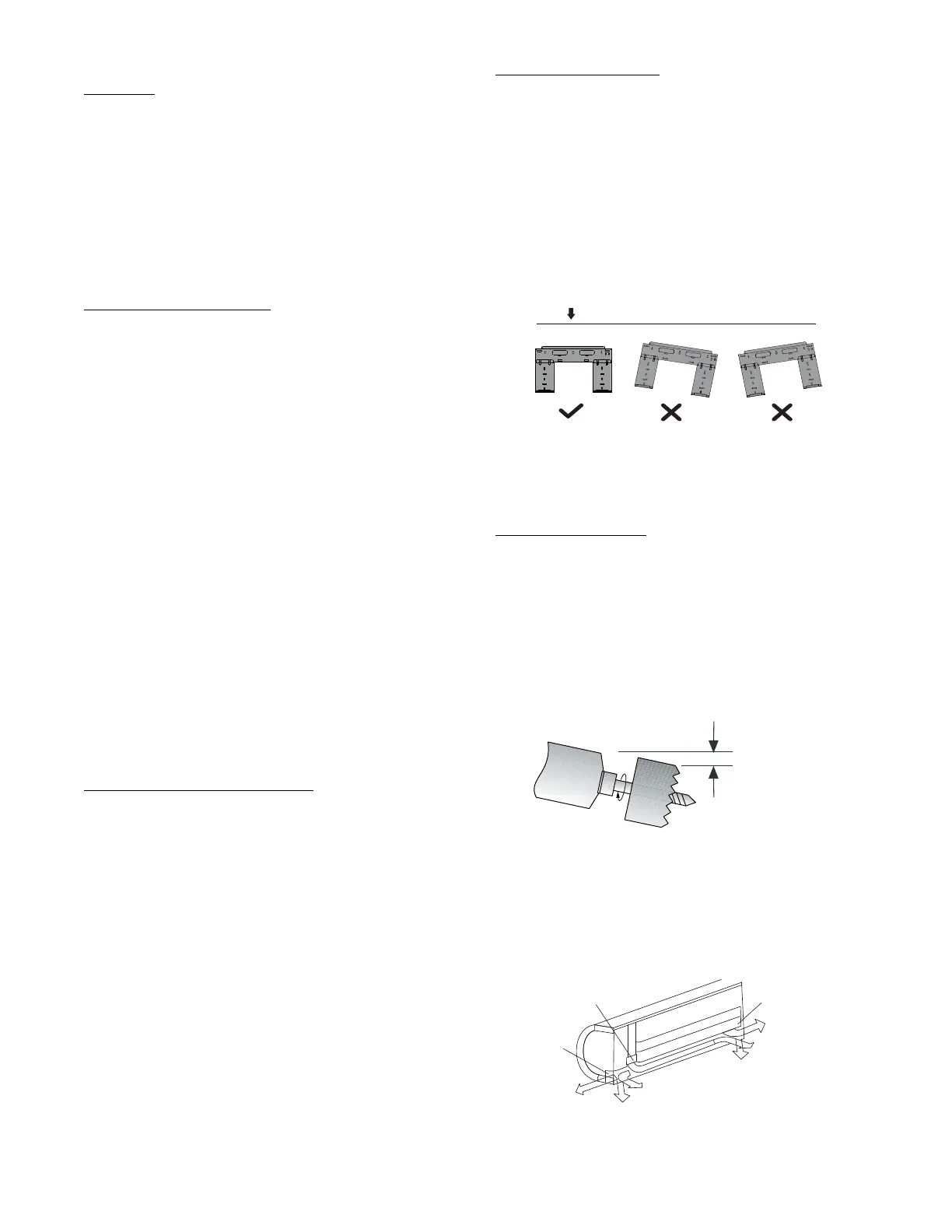
If piping is going through the back:
1. Determine the pipe hole position using the mounting plate as a
template. Drill the pipe hole diameter per values given in Fig.
3. The outside pipe hole is 1/2−in. (13 mm) min. lower than
the inside pipe hole, so it slants slightly downward (see Fig. 8).
1/2 in. (13 mm
Min.
NDOOR
OUTDOOR
A07371
Fig. 8 - Drill Holes
If piping is going through the right or left side:
1. Use a small saw blade to carefully remove the corresponding
plastic covering on the side panel and drill the appropriate size
hole where the pipe is going through the wall.
Pipe holder
Pipe cover
Right piping
Left piping
Pipe cover
Right back piping
Left back piping
1
2
3
4
A14349
Fig. 9 - Piping Locations
 Loading...