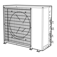
DIMENSIONAL DRAWING — BASE UNIT — 538A018-024 CONDENSING UNITS
UNIT
538A
AB CDEFGH
ft-in. mm ft-in. mm ft-in. mm ft-in. mm ft-in. mm ft-in. mm ft-in. mm ft-in. mm
018 2-1
1
⁄
8
638.2 3-0
15
⁄
16
938.2 1-2
9
⁄
16
369.9 1-4 406.4 1-11
7
⁄
16
595.3 1-5
3
⁄
16
436.6 1-5
1
⁄
2
444.5 1-8
1
⁄
8
511.2
024 2-1
1
⁄
8
638.2 3-0
15
⁄
16
938.2 1-2
9
⁄
16
369.9 1-4 406.4 1-11
7
⁄
16
595.3 1-5
3
⁄
16
436.6 1-5
1
⁄
2
444.5 1-8
1
⁄
8
511.2
UNIT
538A
JK L MNRS
OPERATING
WT
ft-in. mm ft-in. mm ft-in. mm ft-in. mm ft-in. mm ft-in. mm ft-in. mm Lb kg
018 1-1
1
⁄
4
336.6 0-6
5
⁄
8
168.3 0-10
13
⁄
16
274.6 0-0
5
⁄
8
15.00 0-0
3
⁄
8
9.52 0-4
1
⁄
2
115.0 0-6
1
⁄
2
166.0 150 68.0
024 1-2
7
⁄
16
366.7 0-6
3
⁄
4
171.4 1- 0 304.8 0-0
5
⁄
8
15.00 0-0
3
⁄
8
9.52 0-4
1
⁄
2
115.0 0-6
1
⁄
2
166.0 154 69.0
MINIMUM MOUNTING PAD DIMENSIONS
Support Feet Snow Stand Ice Stand
ft-in. mm ft-in. mm ft-in. mm
1-11 x
3-6
584.2 x
1066.8
2-2 x
3-6
660.4 x
1066.8
2-2 x
3-6
660.4 x
1066.8
NOTES:
1. Required clearances, with coil facing wall, allow
6 in. minimum clearance on coil side and coil end,
and 3 ft minimum clearance on compressor end
and fan side. With fan facing wall, allow 8 in. mini-
mum clearance on fan side and coil end, and 3 ft
minimum clearance on compressor end and coil
side. With multi-unit application, arrange units so
discharge of one does not enter inlet of another.
2. Dimensions in parenthesis are in millimeters.
3. Center of Gravity.
10