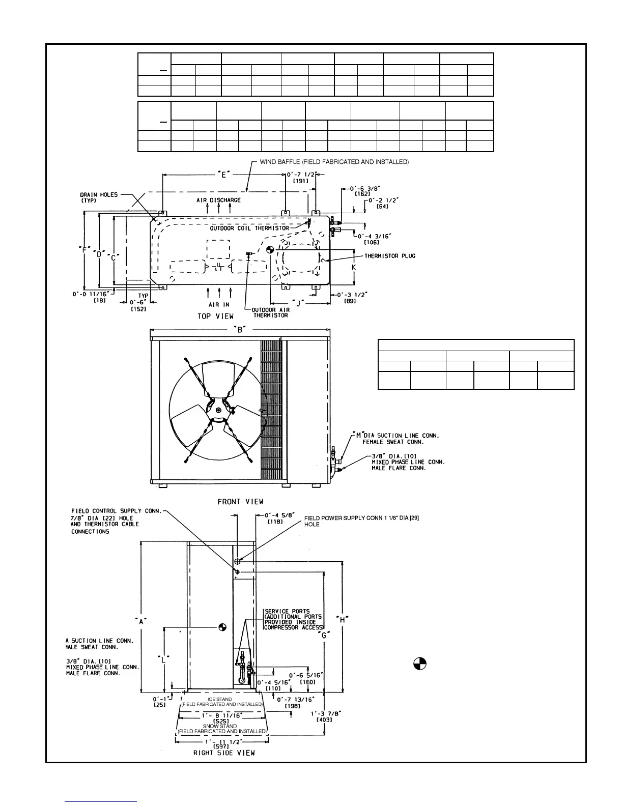
DIMENSIONAL DRAWING, BASE UNIT — 538D018,024 HEAT PUMP UNITS
UNIT
538D
AB CDEF
ft-in. mm ft-in. mm ft-in. mm ft-in. mm ft-in. mm ft-in. mm
018 2-1
1
⁄
8
638.2 3-0
15
⁄
16
938.2 1-2
9
⁄
16
369.9 1-4 406.4 1-11
7
⁄
16
595.3 1-5
3
⁄
16
436.6
024 2-1
1
⁄
8
638.2 3-0
15
⁄
16
938.2 1-2
9
⁄
16
369.9 1-4 406.4 1-11
7
⁄
16
595.3 1-5
3
⁄
16
436.6
UNIT
538D
GHJK L M
OPERATING
WEIGHT
ft-in. mm ft-in. mm ft-in. mm ft-in. mm ft-in. mm ft-in. mm lb Kg
018 1-5
1
⁄
2
444.5 1-8
1
⁄
8
511.2 1-1 330.2 0-6
5
⁄
8
168.3 0-11
1
⁄
4
285.8 0-0
5
⁄
8
15.88 154 69.8
024 1-5
1
⁄
2
444.5 1-8
1
⁄
8
511.2 1-1 330.2 0-6
3
⁄
4
171.5 0-11
5
⁄
8
295.3 0-0
5
⁄
8
15.88 167 75.7
MINIMUM MOUNTING PAD DIMENSIONS
Support Feet Snow Stand Ice Stand
ft-in. mm ft-in. mm ft-in. mm
1-11 x
3-6
584.2 x
1066.8
2-2 x
3-6
660.4 x
1066.8
2-2 x
3-6
660.4 x
1066.8
NOTES:
1. Required clearances, with coil facing wall; allow
6 in. minimum clearance on coil side and coil end,
and 3 ft minimum clearance on compressor end
and fan side. With fan facing wall; allow 8 in. mini-
mum clearance on fan side and coil end, and 3 ft
minimum clearance on compressor end and coil
side. With multi-unit application; arrange units so
discharge of one does not enter inlet of another.
2. Dimensions in [ ] are in millimeters.
3. Center of gravity.
LEGEND
CONN — Connection
11