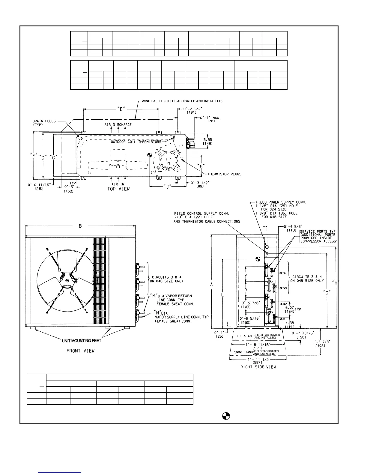
DIMENSIONAL DRAWING, BASE UNIT — 538S CONDENSING UNITS
UNIT
538S
ABCDEFGH
Ft-in. mm Ft-in. mm Ft-in. mm Ft-in. mm Ft-in. mm Ft-in. mm Ft-in. mm Ft-in. mm
024 2-1
1
⁄
8
638 3-0
15
⁄
16
938 1-2
9
⁄
16
370 1-4 406 1-11
7
⁄
16
595 1-5
3
⁄
16
437 1-5
1
⁄
2
445 1-8
1
⁄
8
511
048 3-1
3
⁄
16
945 3-8
9
⁄
16
1132 1-5
1
⁄
16
433 1-6
7
⁄
16
468 2- 6
1
⁄
2
775 1-7
5
⁄
8
499 2-5
5
⁄
8
753 2-8
3
⁄
16
818
UNIT
538S
JKLMNRS
OPERATING
WEIGHT
Ft-in. mm Ft-in. mm Ft-in. mm Ft-in. mm Ft-in. mm Ft-in. mm Ft-in. mm Lb Kg
024 1-2
7
⁄
16
367 0-6
3
⁄
4
171 1-0 305 0-0
5
⁄
8
16 0-0
3
⁄
8
10 — — — — 159 72.0
048 1-2
3
⁄
4
375 0-7
1
⁄
2
191 1-6 457 0-0
5
⁄
8
16 0-0
3
⁄
8
10 0-6
5
⁄
16
160 0-5
7
⁄
8
149 292 132.3
UNIT
538S
MINIMUM MOUNTING PAD DIMENSIONS
SUPPORT FEET SNOW STAND ICE STAND
Ft-in. mm Ft-in. mm Ft-in. mm
024 1-11 x 3-6 584 x 1067 2-2 x 3-6 660 x 1067 2-2 x 3-6 660 x 1067
048 2-0 x 4-2 610 x 1270 2-4 x 4-4 711 x 1270 2-2 x 4-2 660 x 1270
NOTES:
1. Required clearances: with coil facing wall; allow 6 in. mini-
mum clearance on coil side and coil end, and 3 ft minimum
clearance on compressor end and fan side. With fan facing
wall; allow 8 in. minimum clearance on fan side and coil
end, and 3 ft minimum clearance on compressor end and
coil side. With multi-unit application: arrange units so dis-
charge of one does not enter inlet of another.
2. Dimensions in [ ] are in millimeters.
3. Center of gravity.
12