10
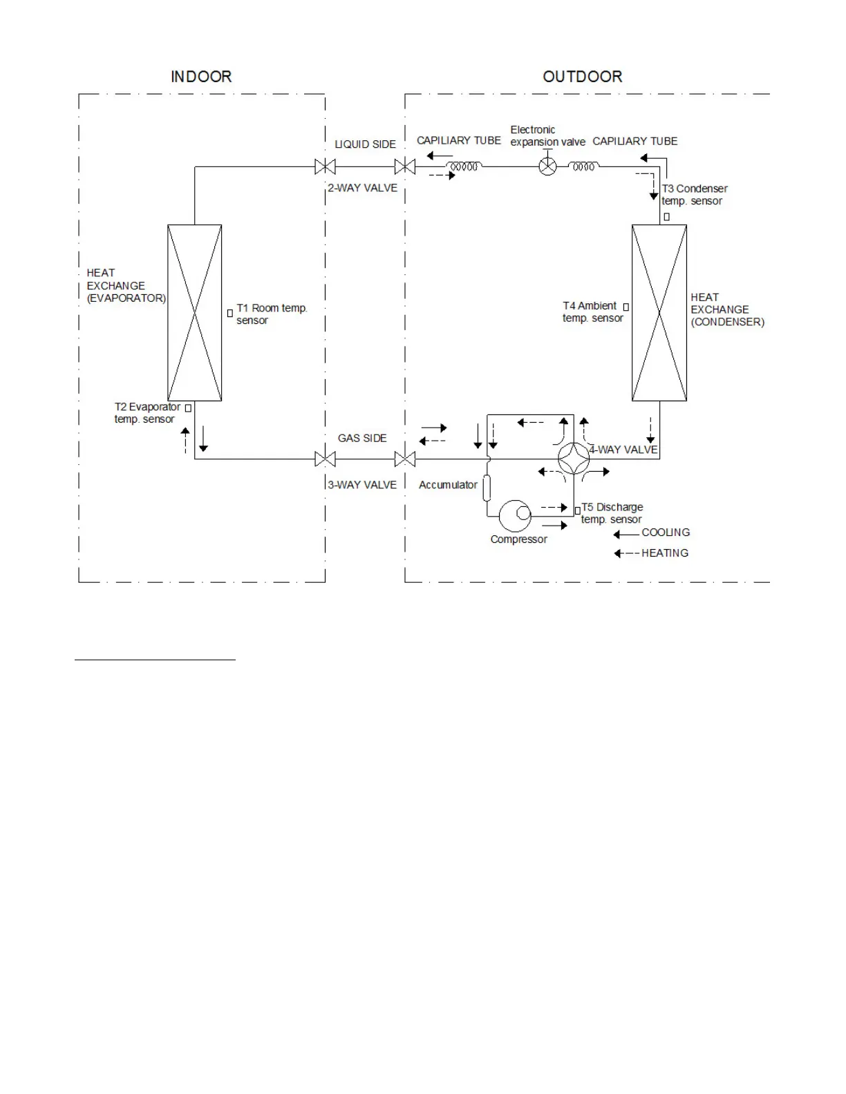
REFRIGERATION CYCLE DIAGRAM
Fig. 6 – Refrigerant Cycle Diagram
REFRIGERANT LINES
General refrigerant line sizing:
1 The outdoor units are shipped with a full charge of R410A
refrigerant. All charges, line sizing, and capacities are based on
runs of 25 ft. (7.6 m). For runs over 25 ft. (7.6 m), consult the
product data.
2 Minimum refrigerant line length between the indoor and
outdoor units is 10 ft. (3 m).
3 Refrigerant lines should not be buried in the ground. If it is
necessary to bury the lines, not more than 36−in. (914 mm)
should be buried. Provide a minimum 6−in. (152 mm) vertical
rise to the service valves to prevent refrigerant migration.
4 Both lines must be insulated. Use a minimum of 1/2−in.
(12.7 mm) thick insulation. Closed−cell insulation is
recommended in all long−line applications.
5 Special consideration should be given to isolating
interconnecting tubing from the building structure. Isolate
the tubing so that vibration or noise is not transmitted into
the structure.
6 For piping runs greater than 25 ft. (7.6 m), add refrigerant
up to the allowable length as specified in the product data.
 Loading...