8
WIRING DIAGRAMS
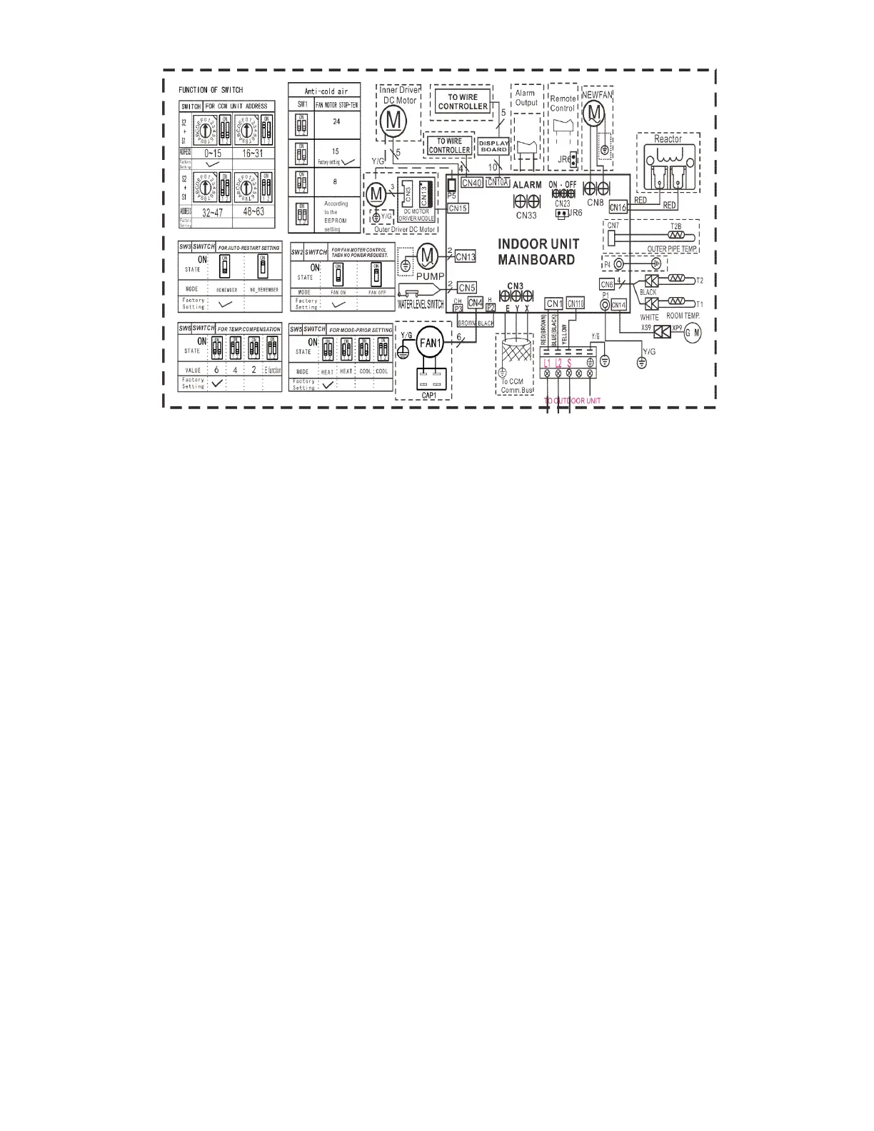
Fig. 4 – Wiring Diagram Sizes 09 − 12
Table 5—Dimensions Sizes 09 − 12
INDOOR UNIT
CODE PART NAME
CN1 Input: 230VAC High voltage Connection of the terminal
CN3 Output: 0-5VDC Connection of the CCM
P1 Output: 0V Connection of the earth
CN5 Output: 1-5VDC Connection of the Water level switch
CN6 Output: 5VDC Connection of the Room and Pipe temperature
CN10A Output: 12VDC Connection of the Display board
CN13 Output: 220VAC High voltage Connection of the Pump
CN14 Output: 12VDC Connection of the Swing motor
CN15 Output: 320VDC High voltage Connection of the DC Fan
CN16 Output: 320VDC High voltage Connection of the Reactor
CN23 Output: 1-12VDC Connection of the Remote switch
CN33 Output: 0V Connection of the Alarm
CN40 Output: 12VDC Connection of the Wire controller
CN110 Output: 24VDC between Pin2 of CN1 connection of the S signal
 Loading...