33
IPM Continuity Check
Turn off the power, let the large capacity electrolytic capacitors discharge completely, and dismount the IPM. Use a digital tester to measure
the resistance between P and UVWN; UVW and N.
Table 12— IPM Continuity Check
Digital Tester Normal Resistance value Digital Tester Normal Resistance Value
(+) Red (-) Black
∞
(Several M W)
(+) Red (-) Black
∞
(Several M W)
P
N U
N
U V
V W
W (+) Red
Pressure on Service Port
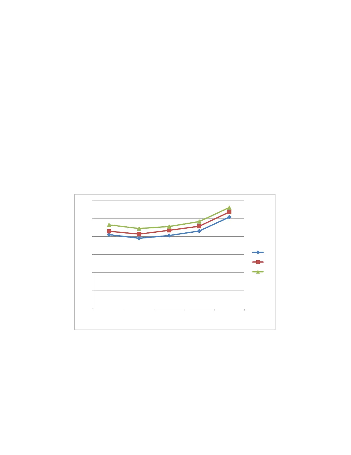
Table 13—Cooling Chart
_F _C Indoor Temp.
Outdoor Temp.
75 (23.89) 85 (29.44) 95 (35) 105 (40.56) 115 (46.11)
BAR 70 8.2 7.8 8.1 8.6 10.1
BAR 75 8.6 8.3 8.7 9.1 10.7
BAR 80 9.3 8.9 9.1 9.6 11.2
PSI 70 119 113 117 125 147
PSI 75 124 120 126 132 155
PSI 80 135 129 132 140 162
MPA 70 0.82 0.78 0.81 0.86 1.01
MPA 75 0.86 0.83 0.87 0.91 1.07
MPA 80 0.93 0.89 0.91 0.96 1.12
0.0
2.0
4.0
6.0
8.0
10.0
12.0
75 㸦23.89㸧85 㸦29.44㸧
95
㸦35㸧
105 㸦40.56 㸧115 㸦46.11㸧
70
75
80
Pressure (bar)
Outdoor temp.
Fig. 42 – Pressure Bar
 Loading...