986TC: Installation, Start-up, Operating, Service and Maintenance Instructions
Manufacturer reserves the right to change, at any time, specifications and designs without notice and without obligations.
29
A12222
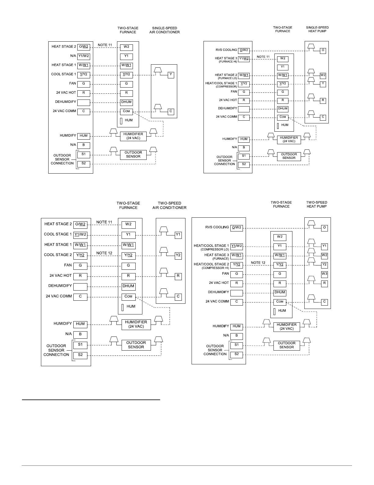
Fig. 40 – Thermostat Wiring Diagrams
NOTES FOR THERMOSTAT WIRING DIAGRAMS
1. Heat pump MUST have a high pressure switch for HYBRIDHEATr dual fuel applications.
2. Refer to outdoor equipment Installation Instructions for additional information and setup procedure.
3. If the heat pump date code is 1501E or earlier, select the “ZONE” position on the two speed heat pump control. Heat pumps with date code 1601E
and later do not have or require a “ZONE” selection.
4. Outdoor Air Temperature Sensor must be attached in all HYBRIDHEATr dual fuel applications.
5. Configure the thermostat for air conditioner installations. Refer to thermostat instructions.
6. Configure thermostat for heat pump installations. Refer to thermostat instructions.
Modulating and 2-Stage Furnace with Single-Speed Air Conditioner
Modulating and 2-Stage Furnace with Two-Speed Air Conditioner
Modulating and 2-Stage Furnace with Single-Speed Heat Pump
Modulating and 2-Stage Furnace with Two-Speed Heat Pump
See notes 2, 5, 7, 10, 11, 16, and 17 See notes 1, 2, 4, 6, 7, 9, 10, 11, 15, 16, and 17
THERMOSTAT
THERMOSTAT
THERMOSTAT
THERMOSTAT
D
D
D
D
See notes 2, 5, 8, 10, 11, 12, 16, and 17
See notes 1, 2, 3, 4, 6, 8, 9, 10, 12, 13, 15, 16, and 17

 Loading...