EasyManua.ls Logo

Bryant 987MB User Manual

Bryant 987MB
76 pages
To Next Page IconTo Next Page
Page #1 background imageLoading...
Page #1 background image
Installation, Start-up, Operating and Service
and Maintenance Instructions
NOTE: Read the entire instruction manual before starting the
installation.
TABLE OF CONTENTS
REQUIRED NOTICE FOR MASSACHUSETTS INSTALLATIONS
IMPORTANT . . . . . . . . . . . . . . . . . . . . . . . . . . . . . . . . . . . . . . . . . . . 2
SAFETY CONSIDERATIONS . . . . . . . . . . . . . . . . . . . . . . . . . . . . . 3
Table 1 Minimum Clearances to Combustible Materials for All Units
4
INTRODUCTION . . . . . . . . . . . . . . . . . . . . . . . . . . . . . . . . . . . . . . . 5
Table 2 – Loose Parts Bag . . . . . . . . . . . . . . . . . . . . . . . . . . . . . . . 5
CODES AND STANDARDS. . . . . . . . . . . . . . . . . . . . . . . . . . . . . . . 6
ELECTROSTATIC DISCHARGE (ESD) PRECAUTIONS PROCE-
DURE . . . . . . . . . . . . . . . . . . . . . . . . . . . . . . . . . . . . . . . . . . . . . . . . . 6
ACCESSORIES . . . . . . . . . . . . . . . . . . . . . . . . . . . . . . . . . . . . . . . . . 7
LOCATION . . . . . . . . . . . . . . . . . . . . . . . . . . . . . . . . . . . . . . . . . . . . 7
AIR FOR COMBUSTION AND VENTILATION . . . . . . . . . . . . . . 8
Table 3 – Minimum Free Area Required for Each Combustion Air
Opening or Duct to Outdoors. . . . . . . . . . . . . . . . . . . . . . . . . . . . . 9
Table 4 – Minimum Space Volumes for 100% Combustion, Ventila-
tion and Dilution Air from Outdoors . . . . . . . . . . . . . . . . . . . . . . . 9
CONDENSATE TRAP. . . . . . . . . . . . . . . . . . . . . . . . . . . . . . . . . . . . 9
CONDENSATE DRAIN CONNECTION . . . . . . . . . . . . . . . . . . . . 11
INSTALLATION . . . . . . . . . . . . . . . . . . . . . . . . . . . . . . . . . . . . . . . 14
Table 5 – Opening Dimensions - In. (mm) . . . . . . . . . . . . . . . . . 16
Table 6 – Filter Information. . . . . . . . . . . . . . . . . . . . . . . . . . . . . 17
AIR DUCTS . . . . . . . . . . . . . . . . . . . . . . . . . . . . . . . . . . . . . . . . . . . 21
Table 7 Cooling4 and Heating Air Delivery - CFM (Bottom Return5
With Filter). . . . . . . . . . . . . . . . . . . . . . . . . . . . . . . . . . . . . . . . . . 21
GAS PIPING. . . . . . . . . . . . . . . . . . . . . . . . . . . . . . . . . . . . . . . . . . . 24
Table 8 – Maximum Capacity of Pipe . . . . . . . . . . . . . . . . . . . . . 25
ELECTRICAL CONNECTIONS. . . . . . . . . . . . . . . . . . . . . . . . . . . 26
Table 9 – Electrical Data . . . . . . . . . . . . . . . . . . . . . . . . . . . . . . . 27
VENTING. . . . . . . . . . . . . . . . . . . . . . . . . . . . . . . . . . . . . . . . . . . . . 32
Table 10 – Vent Termination Kit for Direct Vent (2-pipe) Systems35
Table 11 – Maximum Equivalent Vent Length - Ft. . . . . . . . . . . 42
Table 12 – Deductions from Maximum Equivalent Vent Length - Ft.
(M) . . . . . . . . . . . . . . . . . . . . . . . . . . . . . . . . . . . . . . . . . . . . . . . . 43
Table 13 Maximum Allowable Exposed Vent Lengths Insulation Ta-
ble. . . . . . . . . . . . . . . . . . . . . . . . . . . . . . . . . . . . . . . . . . . . . . . . . 46
Maximum Allowable Exposed Vent Length in Unconditioned Space - Ft.
46
Maximum Allowable Exposed Vent Length in Unconditioned Space -
Meters . . . . . . . . . . . . . . . . . . . . . . . . . . . . . . . . . . . . . . . . . . . . . . . . 46
Table 14 – Hanger Spacing . . . . . . . . . . . . . . . . . . . . . . . . . . . . . 48
Table 15 – Approved Combustion-Air and Vent Pipe, Fitting and Ce-
ment Materials . . . . . . . . . . . . . . . . . . . . . . . . . . . . . . . . . . . . . . . 49
START-UP, ADJUSTMENT, AND SAFETY CHECK . . . . . . . . . 51
Table 16 – Altitude Derate Multiplier for U.S.A.* . . . . . . . . . . . 53
Table 17 – Gas Rate (CU ft./hr). . . . . . . . . . . . . . . . . . . . . . . . . . 55
Table 18 – Blower Off Delay Setup Switch . . . . . . . . . . . . . . . . 57
Table 19 Orifice Size and Manifold Pressure (In. W.C.) for Gas Input
Rate . . . . . . . . . . . . . . . . . . . . . . . . . . . . . . . . . . . . . . . . . . . . . . . 59
Table 20 Orifice Size and Manifold Pressure (In. W.C.) for Gas Input
Rate . . . . . . . . . . . . . . . . . . . . . . . . . . . . . . . . . . . . . . . . . . . . . . . 59
SERVICE AND MAINTENANCE PROCEDURES. . . . . . . . . . . . 60
Winterization . . . . . . . . . . . . . . . . . . . . . . . . . . . . . . . . . . . . . . . . . . 66
SEQUENCE OF OPERATION . . . . . . . . . . . . . . . . . . . . . . . . . . . . 70
PARTS REPLACEMENT INFORMATION GUIDE . . . . . . . . . . . 76
MODEL NOMENCLATURE . . . . . . . . . . . . . . . . . . . . . . . . . . . . . 76
TRAINING. . . . . . . . . . . . . . . . . . . . . . . . . . . . . . . . . . . . . . . . . . . . 76
A200352
Most states in the USA and jurisdictions in Canada have laws that
require the use of Carbon Monoxide (CO) alarms with fuel burning
products. Examples of fuel burning products are furnaces, boilers, space
heaters, generators, water heaters, stoves/ranges, clothes dryers,
fireplaces, incinerators, automobiles, and other internal combustion
engines. Even if there are no laws in your jurisdiction requiring a CO
Alarm, it’s highly recommended that whenever any fuel burning product
is used in or around the home or business that the dwelling be equipped
with a CO Alarm(s). The Consumer Product Safety Commission
recommends the use of CO Alarm(s). The CO Alarm(s) must be
installed, operated, and maintained according to the CO Alarm
manufacturer’s instructions. For more information about Carbon
Monoxide, local laws, or to purchase a CO Alarm online, please visit the
following website. https://www.kidde.com.
Portions of the text and tables are reprinted from NFPA 54/ANSI Z223.1E, with permission of National Fire Protection Association, Quincy, MA
02269 and American Gas Association, Washington DC 20001. This reprinted material is not the complete and official position of the NFPA or ANSI
on the referenced subject, which is represented only by the standard in its entirety.
987MB
Modulating, High Efficiency Condensing Gas
Furnace, 4-Way Multipoise
WARNING
!
CARBON MONOXIDE POISONING HAZARD
Failure to follow this warning could result in personal injury and/or
death.
Carbon Monoxide (CO) is a colorless, odorless, and tasteless poisonous
gas that can be fatal when inhaled. Follow all installation, maintenance,
and service instructions. See additional information below regarding
the installation of a CO Alarm.
Question and Answer IconNeed help?

Do you have a question about the Bryant 987MB and is the answer not in the manual?

Bryant 987MB Specifications

General IconGeneral
Model987MB
Heating Capacity40, 000 - 120, 000 BTU/h
Cabinet TypeMulti-Position
Ignition TypeHot Surface Ignition
Heat Exchanger MaterialStainless Steel
Fuel TypeNatural Gas
Blower MotorVariable Speed
Warranty10-Year Parts
StagesTwo-Stage

Summary

Required Notice for Massachusetts Installations

Safety Considerations

Important Installation and Start-up Procedures

Codes and Standards

Location

General

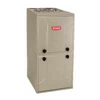
General guidelines for furnace placement and clearances.

Air for Combustion and Ventilation

Introduction

Overview of air requirements for furnace operation.

Direct Vent (2-pipe) Applications

Requirements for direct-vent systems.

Ventilated Combustion Air Applications (for U.S. Only)

Requirements for ventilated combustion air systems.

Condensate Trap

Condensate Trap-Downflow Orientation

Instructions for orienting the condensate trap in downflow.

Condensate Trap-Upflow Orientation

Instructions for orienting the condensate trap in upflow.

Condensate Drain Connection

Upflow/Downflow Orientation

Routing condensate drain lines in upflow/downflow.

For Right Side Condensate Drain:

Steps for connecting drain to the right side.

For Left Side Condensate Drain Connection:

Steps for connecting drain to the left side.

INSTALLATION

Upflow Installation

Specifics for upflow installation.

Supply Air Connections

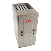
Guidelines for connecting supply air ducts.

Return Air Connections

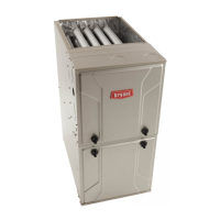
Guidelines for connecting return air ducts.

Bottom Return Air Inlet

Connecting the bottom return air inlet.

Filter Arrangement

Filter and Return Duct Sizing

Sizing filters and ductwork for optimal airflow.

AIR DUCTS

General Requirements

General guidelines for duct system design and installation.

Return Duct Sizing

Sizing considerations for return ductwork.

GAS PIPING

ELECTRICAL CONNECTIONS

115-V Wiring

Wiring requirements for 115-volt power supply.

J-Box Installation

External Electrical Box on Furnace Casing

Installing an external electrical box.

For a side-mounted external electrical box, complete the following:

Steps for side-mounted external electrical box.

Power Cord Installation in Furnace J-Box

Installing power cords in the J-box.

Accessories

Alternate Power Supplies

Considerations for using alternate power sources.

VENTING

Special Venting Requirements for Installations in Canada

Venting regulations specific to Canada.

General

General venting information.

Venting Systems

Types of venting systems and their requirements.

Locating the Vent Termination

General

General guidelines for vent termination placement.

Ventilated Combustion Air

Termination requirements for ventilated air.

Termination Requirements for the Provinces of Alberta and Saskatchewan

Specific termination rules for Alberta/Saskatchewan.

Venting System Length Calculations

Configure the Furnace

Near Furnace Vent Connections

How to connect vent pipes near the furnace.

Installing the Vent Pipe Adapter and Combustion Air Pipe Adapter

Optional Installation of the Vent Pipe

Optional method for installing vent pipe.

Installing the Vent Termination

Procedures for installing vent terminations.

Roof Terminations

Guidelines for roof vent terminations.

Concentric Vent

Installation of concentric vent terminations.

START-UP, ADJUSTMENT, AND SAFETY CHECK

General

General procedures for start-up and safety checks.

Setup Switches

Configuring furnace settings via setup switches.

Air Conditioning (A/C) Setup Switches (SW2)

Setting up furnace for A/C operation.

Continuous Fan (CF) Setup Switches (SW3)

Setting up furnace for continuous fan operation.

Adjust Temperature Rise

Check Inlet Gas Pressure

Verifying inlet gas pressure.

Adjust Manifold Pressure - Maximum Heat

Setting manifold pressure for maximum heat.

Adjust Manifold Pressure - Minimum Heat

Setting manifold pressure for minimum heat.

Clocking The Meter

Measuring gas input rate using the meter.

Check Safety Controls

1. Check Main Limit Switch

Testing the main limit switch.

2. Check Pressure Switch(es)

Testing the pressure switch.

Checklist

Final checks before leaving the site.

SERVICE AND MAINTENANCE PROCEDURES

Troubleshooting

Guide for diagnosing and resolving furnace issues.

Retrieving Stored Fault Codes

Accessing stored error codes.

Component Self-Test

Cleaning and/or Replacing Air Filter

Procedures for cleaning or replacing air filters.

Blower Motor and Wheel Maintenance

Cleaning Burners and Flame Sensor

Flushing Collector Box and Drainage System

Secondary Heat Exchangers

Servicing secondary heat exchangers.

Wiring Diagrams

Reference to furnace wiring diagrams.

Cleaning Heat Exchangers

Primary Heat Exchangers

Cleaning procedures for primary heat exchangers.

Winterization

Troubleshooting Guide

SEQUENCE OF OPERATION

Cooling Mode

Furnace operation during cooling mode.

1. Single-Speed Cooling

Single-speed cooling operation.

2. Single-Stage Thermostat and Two-Speed Cooling (Adaptive Mode)

Two-speed cooling with single-stage thermostat.

3. Two Stage Thermostat and Two-Speed Cooling

Two-stage cooling with two-stage thermostat.

4. Dehumidification Mode

Operation in dehumidification mode.

Continuous Blower Mode

Furnace operation with continuous blower.

Continuous Blower Speed Selection from Thermostat

Adjusting continuous blower speed via thermostat.

Component Self Test

Performing component self-test.

SERVICE

COMPONENT TEST

Initiating the component test sequence.

PARTS REPLACEMENT INFORMATION GUIDE

Casing Group

Components related to the furnace casing.

Electrical Group

Components related to electrical systems.

Blower Group

Components related to the blower assembly.

Filter Group

Components related to air filters.

Gas Control Group

Components related to gas control.

Heat Exchanger Group

Components related to heat exchangers.

Inducer Group

Components related to the inducer assembly.

MODEL NOMENCLATURE

TRAINING

Related product manuals