987MB: Installation, Start-up, Operating and Service and Maintenance Instructions
Manufacturer reserves the right to change, at any time, specifications and designs without notice and without obligations.
54
BTUh min-heat per burner or Table 14 for 20,200 BTUh
Max-Heat/8,000 BTUh Min-Heat per burner.
4. Find closest natural gas heat value and specific gravity in Table 13
or Table 14 depending on furnace gas input rate.
5. Follow heat value and specific gravity lines to point of intersection
to find orifice size and maximum and minimum manifold pressure
settings for proper operation.
6. Check and verify burner orifice size in furnace. NEVER ASSUME
ORIFICE SIZE. ALWAYS CHECK AND VERIFY.
7. Replace original orifice with correct size, if required by Table 13 or
Table 14 depending on furnace gas input rate. Use only
factory-supplied orifices, see EXAMPLE 1.
EXAMPLE 1 - 80,000 BTUH INPUT:
EXAMPLE: 0 - 2000 ft. (0 - 609.6M) altitude
Heating value = 1050 Btu/cu ft.
Specific gravity = 0.62
Therefore: Orifice No. 44
* Furnace is shipped with No. 44 orifices. In this example, all main
burner orifices are the correct size and do not need to be changed to
obtain proper input rate.
Manifold pressure: 3.4-in. w.c. for maximum heat, 0.55-in. w.c. for
minimum heat.
NOTE: To convert gas manifold Table pressures to Pascals, multiply the
in. w.c. value by 249.1 Pa/in. w.c. (1 in. w.c. = 249.1 Pa).
Check Inlet Gas Pressure
The inlet gas pressure must be checked with the furnace operating in
maximum heat. This is necessary to make sure the inlet gas pressure
does not fall below the minimum pressure of 4.5 in. w.c. for natural gas.
The maximum inlet gas pressure is 13.6 in. of water column. If the inlet
pressure is too low, you will not be able to adjust the manifold pressure
to obtain the proper input rate. To check the inlet gas pressure:
1. Make sure the gas supply is turned off to the furnace and at the
electric switch on the gas valve.
2. Loosen set screw on inlet tower pressure tap no more than one full
turn with a 3/32-in. hex wrench or remove the 1/8 in. NPT plug
from the inlet pressure tap on the gas valve.
3. Connect a manometer to the inlet pressure tap on gas valve.
4. Turn on furnace power supply.
5. Turn gas supply manual shutoff valve to ON position.
6. Turn furnace gas valve switch to ON position.
7. Jumper the R to W/W1 and W2 thermostat connections at the
furnace control board.
8. When main burners ignite, confirm inlet gas pressure is Between
4.5 in. w.c. and 13.6 in. w.c.
9. Remove jumper across thermostat connections to terminate call for
heat. Wait until the blower off delay is completed.
10. Turn furnace gas valve electric switch to OFF position.
11. Turn gas supply manual shutoff valve to OFF position.
12. Turn off furnace power supply.
13. Remove manometer from the inlet pressure tap of the gas valve.
14. Tighten set screw on inlet tower pressure tap with 3/32-in. hex
wrench, or if 1/8-in. NPT plug was removed, apply pipe dope
sparingly to end of plug and re-install in the gas valve.
Adjust Manifold Pressure - Maximum Heat
For proper operation and long term reliability, the manifold pressure
must be adjusted within +/-2 percent of input rate on furnace rating plate.
The modulating furnace manifold pressure is set at two points. The first
point is Maximum Heat. The second point is Minimum Heat. Do not
adjust Intermediate Heat manifold pressure. Intermediate Heat manifold
pressure is checked as part of the temperature rise, but is not adjustable.
Always adjust Maximum Heat first, then Minimum Heat.
To adjust manifold pressure to obtain input rate for Maximum Heat:
1. Make sure the gas supply is turned off to the furnace and at the
electric switch on the gas valve.
2. Loosen set screw on manifold tower pressure tap no more than one
full turn with a 3/32-in. hex wrench, or remove the 1/8 in. NPT plug
from the manifold pressure tap on the gas valve, see Fig. 58.
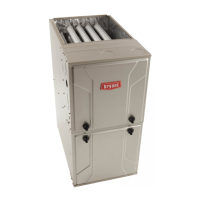
A170116
Fig. 63 – Gas Valve with Tower Pressure Ports
3. Connect a manometer to the outlet pressure tap on gas valve.
4. Turn on furnace power supply.
5. Turn gas supply manual shutoff valve to ON position.
6. Turn furnace gas valve switch to ON position.
7. Jumper the R to W/W1 and W2 thermostat connections at the
furnace control board.
8. After the main burners ignite and the blower starts, confirm
Maximum Heat manifold pressure is correct, based on the manifold
pressure tables in the installation instructions.
9. To adjust the Maximum Heat manifold pressure, slowly turn
adjusting screw counterclockwise to decrease manifold pressure or
clockwise to increase manifold pressure. Turn adjustment no more
NOTICE
!
If orifice hole appears damaged or it is suspected to have been redrilled,
check orifice hole with a numbered drill bit of correct size. Never
redrill an orifice. A burr-free and squarely aligned orifice hole is
essential for proper flame characteristics.
WARNING
!
FIRE HAZARD
Failure to follow this warning could result in personal injury, death,
and/or property damage.
Inlet pressure tap set screw must be tightened and ⅛-in. NPT pipe plug
must be installed to prevent gas leaks.
NOTICE
!
DO NOT set Maximum Heat manifold pressure less than 3.2-in. w.c. or
more than 3.8 in. w.c. for natural gas. If required manifold pressure is
outside this range, change main burner orifices to obtain manifold
pressure in this range.