987MB: Installation, Start-up, Operating and Service and Maintenance Instructions
Manufacturer reserves the right to change, at any time, specifications and designs without notice and without obligations.
55
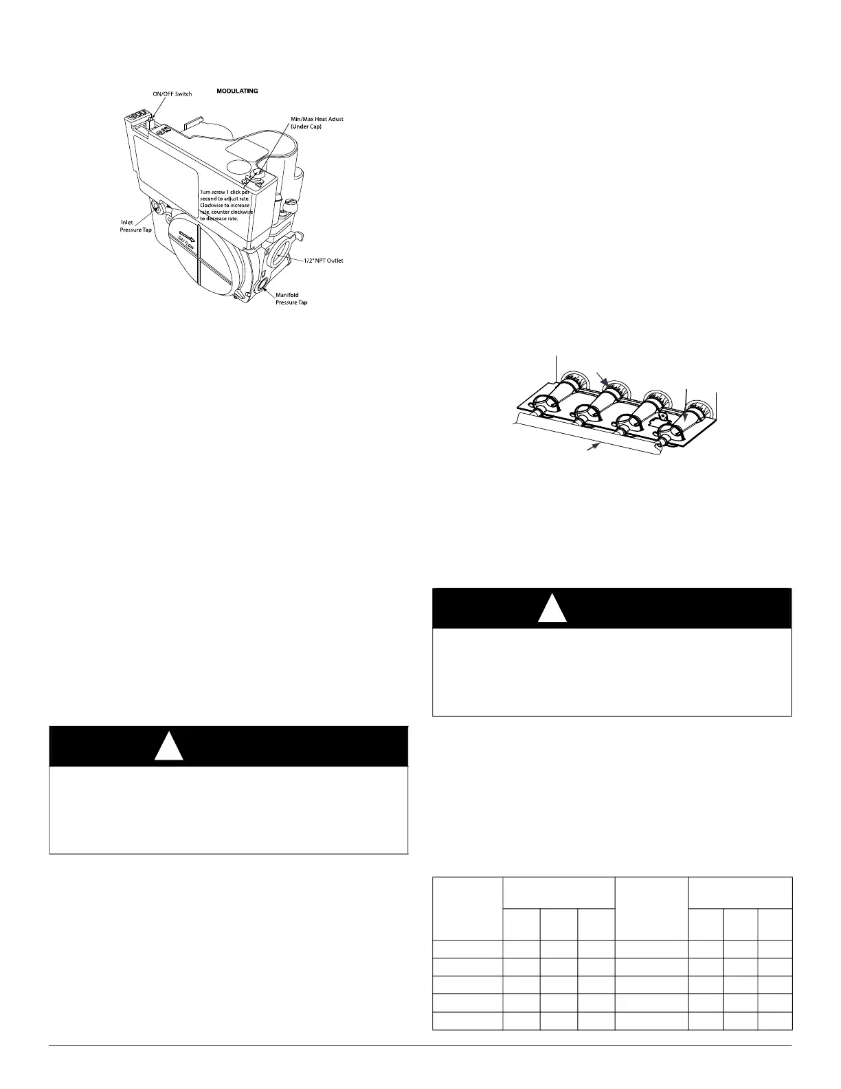
than one click per second until you obtain the required manifold
pressure, see Fig. 64.
A10496
Fig. 64 – Gas Valve without Tower Pressure Ports
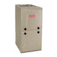
10. Main burner flame should be clear blue, almost transparent.
11. After adjusting the Maximum Heat manifold pressure, remove
jumpers across thermostat connections to terminate the call for
heat.
12. Wait for blower off-delay to finish then reset 115-v power to
furnace.
Adjust Manifold Pressure - Minimum Heat
To adjust manifold pressure to obtain input rate for Minimum Heat:
1. Turn SW1-2 ON and SW4-2 must be OFF.
2. Jumper R and W/W1 thermostat connections on control to start
furnace.
3. After the main burners ignite and the blower starts, confirm
Minimum Heat manifold pressure is correct, based on the manifold
pressure tables in the installation instructions.
4. To adjust the Minimum Heat manifold pressure, slowly turn
adjusting screw counterclockwise to decrease manifold pressure or
clockwise to increase manifold pressure. Turn adjustment no more
than one click per second until you obtain the required manifold
pressure, see Fig. 64.
5. After adjusting the manifold pressure, remove jumpers across
thermostat connections to terminate the call for heat. Wait until the
blower off delay is completed.
6. Move setup switch SW1-2 to the OFF position.
Clocking The Meter
Verify natural gas input rate by clocking meter.
NOTE: Contact your HVAC distributor or gas supplier for metric gas
meter Tables, if required.
1. Turn off all other gas appliances and pilots served by the meter.
2. Move setup switches SW1-2 to ON position and SW4-2 to OFF.
This keeps furnace locked in low--heat operation when only W/W1
is energized or high heat operation when R to W/W1 and W2 are
jumpered.
3. Jumper R to W/W1 and W2. Run furnace for 3 minutes in
maximum heat operation.
4. Measure time (in sec) for gas meter to complete one revolution and
note reading. The 2 or 5 cubic feet dial provides a more accurate
measurement of gas flow.
5. Refer to Table 17 for cubic ft. of gas per hr. Multiply gas rate cu
ft./hr by heating value (BTUh/cu ft.) to obtain input rate.
6. If clocked rate does not match required input from Step 5, increase
manifold pressure to increase input or decrease manifold pressure
to decrease input. Repeat steps 3 through 5 until correct maximum
heat input is achieved. See Fig. 59.
NOTE: Setup switches SW1-2 must be ON and SW4-2 must be OFF.
This keeps furnace locked in minimum heat operation when R to W/W1
is energized. Repeat items 3 through 6 for minimum heat operation until
minimum heat input is achieved.
7. Remove jumpers across thermostat connections to terminate the
call for heat. Wait until the blower off delay is completed then reset
115-v power to furnace.
8. Restore furnace to normal operating condition.
A11461
Fig. 65 – Burner Flame
9. Remove jumpers across thermostat connections to terminate the
call for heat. Wait until the blower off delay is completed.
10. Disconnect 115 VAC power to furnace.
11. Turn gas valve ON/OFF switch to OFF.
12. Remove water column manometer or similar device from manifold
pressure tap.
13. Tighten set screw on manifold tower pressure tap with 3/32-in hex
wrench, or if 1/8-in. NPT plug was removed, apply pipe dope
sparingly to end of plug and reinstall in the gas valve.
14. Turn gas valve ON/OFF switch to ON.
15. Move setup SW1-2 on furnace control to position required for
attached thermostat (OFF for single-stage thermostats, ON for
two-stage thermostats).
16. Check for gas leaks and verify furnace operation.
.
WARNING
!
FIRE HAZARD
Failure to follow this warning could result in personal injury, death,
and/or property damage.
Manifold pressure tap set screw must be tightened and ⅛-in. NPT pipe
plug must be installed to prevent gas leaks.
WARNING
!
FIRE HAZARD
Failure to follow this warning could result in personal injury, death,
and/or property damage.
Manifold pressure tap set screw must be tightened or ⅛-in. NPT pipe
plug must be installed to prevent gas leaks.
Table 17 – Gas Rate (CU ft./hr)
SECONDS
FOR 1 REV
SIZE OF TEST DIAL
SECONDS
FOR 1 REV
SIZE OF TEST
DIAL
1 Cu
Ft.
2 Cu
Ft.
5 Cu
Ft.
1 Cu
Ft.
2 Cu
Ft.
5 Cu
Ft.
10
360 720 1800 50 72 144 360
11
327 655 1636 51 71 141 355
12
300 600 1500 52 69 138 346
13
277 555 1385 53 68 136 340
14
257 514 1286 54 67 133 333
Burner Flame
Burner
Manifold