28
2-IN.
(51 mm)
ROLLOUT PROTECTION REQUIRED
Install 12” x 22” (305x559 mm) sheet metal in front of burner compartment
area. The sheet metal MUST extend underneath the furnace casing by 1-in.
(25 mm) with the door removed. The bottom closure panel may be used for
ame roll-out protection when bottom of furnace is used for return air connection.
30 IN. (762 mm)
MIN. WORK AREA
COMBUSTION - AIR PIPE
(SEE VENTING SECTION)
A150580
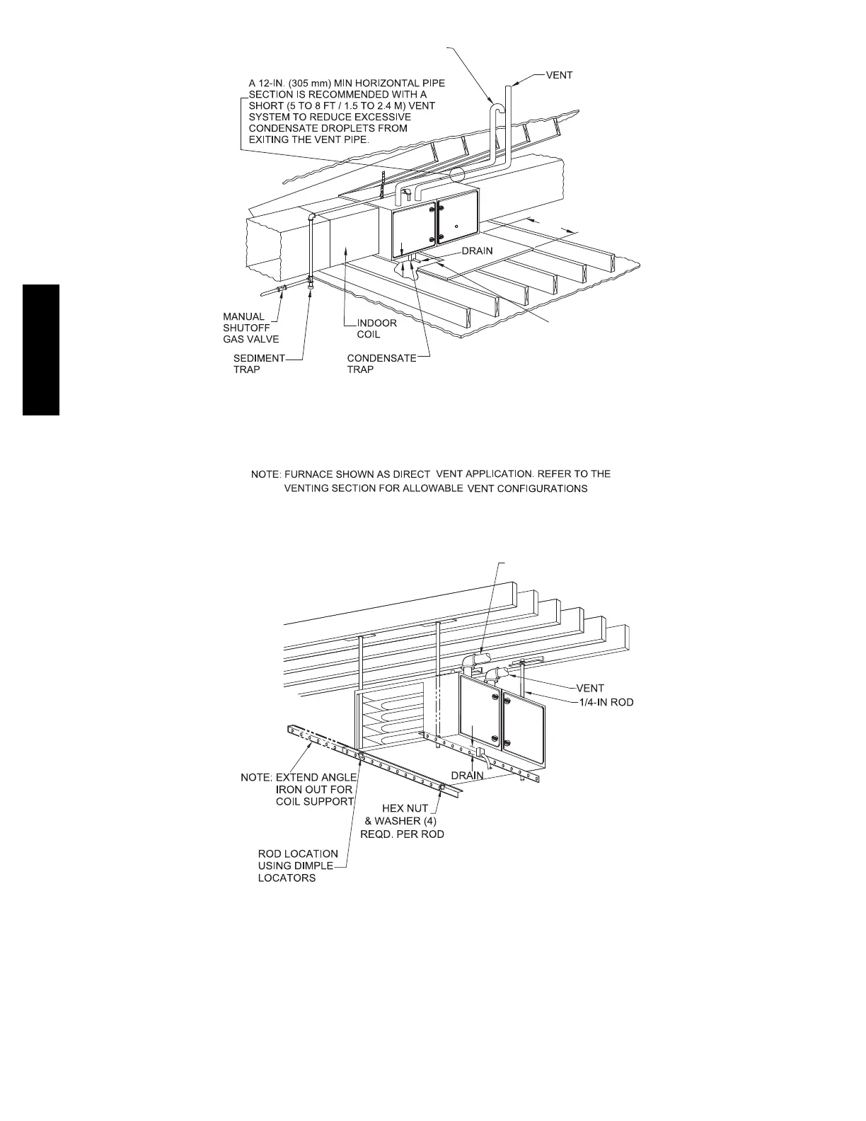
Fig. 30 -- Working Platform for Attic Installation
NOTE: Local codes may r equire a drain pan and condensate trap when a condensing furnace is installed over a finished ceiling.
2-IN.
(51 mm)
COMBUSTION-AIR PIPE
(SEE VENTING SECTION)
Install 12” x 22” (204 x 559 mm) sheet metal in front of and above the burner compartment area.
he sheet metal MUST extend above the furnace casing by 1-in. (25 mm with the door removed.
A 1-in. (25 mm) clearance minimum between top of furnace and combustible material is required.
he entire length of furnace must be supported when furnace is used in horizontal position to
ensure proper drainage.
NOTE: FURNACE SHOWN IS A DIRECT-VENT APPLICATION. REFER TO THE VENTING SECTION FOR
ALLOWABLE VENT CONFIGURATIONS.
ROLLOUT PROTECTION REQUIRED
A150581
Fig. 31 -- Suspended Furnace Installation
NOTE: Local codes may r equire a drain pan and condensate trap when a condensing furnace is installed over a finished ceiling.
915SA
 Loading...