32
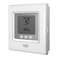
Table 10 – Maximum Capacity of Pipe
NOMINAL
IRON PIPE
SIZE
IN. (MM)
LENGTH OF PIPE --- FT (M)
10
(3.0)
20
(6.0)
30
(9.1)
40
(12.1)
50
(15.2)
1/2 (13) 175 120 97 82 73
3/4 (19) 360 250 200 170 151
1 ( 25) 680 465 375 320 285
1-1/4 (32) 1400 950 770 660 580
1-1/2 (39) 2100 1460 1180 990 900
* Cubic ft of gas per hr for gas pressures of 0.5 psig (14 ---in. w.c.) or less
and a pressure drop of 0.5 ---in. w.c. (based on a 0.60 specific gravity gas).
Ref: Table 10 above and 6.2 of
current edition of NFPA54/ANSI Z223.1.
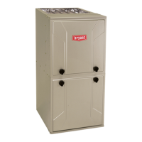
Gas Pipe Grommet Required
For Direct Vent Applications
Left Side Gas Entry. Gas Pipe
Grommet Required For Direct
Vent Applications.
A11338
Fig. 32 -- Gas Entry
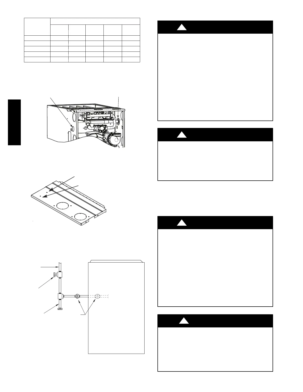
1ï1/2 inch for Gas
7/8 inch for 115 VAC Electric
A170125
Fig. 33 -- Alternate Gas and Electric Entry
NOTE: Top plate may be field drilled for alternate gas and
1 15 VAC electric entry.
GAS
SUPPLY
MANUAL
SHUT OFF
VALVE
(REQUIRED)
SEDIMENT
TRAP
UNION
NOTE: Union may be inside the
vestibule where permitted by
local codes.
FRONT
A11035
Fig. 34 -- Typical Gas Pipe Arrangement
ELECTRICAL CONNECTIONS
ELECTRICAL SHOCK, FIRE OR EXPLOSION
HAZARD
Failure to follow safety warnings could result in
dangerous operation, serious injury, death or property
damage.
Improper servicing could result in dangerous operation,
serious injury, death or property damage.
-- Before servicing, disconnect all electrical power to
furnace.
-- When servicing controls, label all wires prior to
disconnection. Reconnect wires correctly.
-- Verify proper operation after servicing.
-- Always reinstall access doors after completing service
and maintenance.
!
WARNING
ELECTRICAL SHOCK HAZARD
Failure to follow this warning could result in personal
injury or death.
Blower door switch opens 115-- v power to control. No
component operation can occur. Do not bypass or close
switch with blower door removed.
!
WARNING
See Fig. 38 for field wiring diagram showing typical field 115--v
wiring. Check all factory and field electrical connections for
tightness.
Field--supplied wiring shall conform with the limitations of 63_F
(33_C) rise.
ELECTRICAL SHOCK AND FIRE HAZARD
Failure to follow this warning could result in personal
injury, death, or property damage.
The cabinet MUST have an uninterrupted or unbroken
ground according to current edition of NEC NFPA 70 or
local codes to minimize personal injury if an electrical fault
should occur. In Canada, refer to Canadian Electrical Code
CSA C22.1. This may consist of electrical wire, conduit
approved for electrical ground or a listed, grounded power
cord (where permitted by local code) when installed in
accordance with existing electrical codes. Refer to the
power cord manufacturer’s ratings for proper wire gauge.
Do not use gas piping as an electrical ground.
!
WARNING
FURNACE MAY NOT OPERATE HAZARD
Failure to follow this caution may result in intermittent
furnace operation.
Furnace control must be grounded for proper operation or
else control will lock out. Control must remain grounded
through green/yellow wire routed to gas valve and manifold
bracket screw.
CAUTION
!
915SA