EasyManua.ls Logo

Bryant Legacy 574D----A User Manual

Bryant Legacy 574D----A
60 pages
To Next Page IconTo Next Page
Page #1 background imageLoading...
Page #1 background image
1
574D----A
LEGACYt 13 SEER SINGLE--PACKAGED AIR CONDITIONER AND
GAS FURNACE SYSTEM WITH PURONR (R--410A) REFRIGERANT
SINGLE AND THREE PHASE
2--5 NOMINAL TONS (SIZES 24--60)
Installation Instructions
NOTE: Read the entire instruction manual before starting the
installation.
NOTE: Installer: Make sure the Owner’s Manual and Service
Instructions are left with the unit after installation.
TABLE OF CONTENTS
PAGE
SAFETY CONSIDERATIONS 1.........................
INTRODUCTION 2...................................
RECEIVING AND INSTALLATION 2--12.................
Check Equipment 2..................................
Identify Unit 2....................................
Inspect Shipment 2.................................
Provide Unit Support 2...............................
Roof Curb 2......................................
Slab Mount 6.....................................
Field Fabricate Ductwork 6............................
Provide Clearances 6.................................
Rig and Place Unit 6.................................
Inspection 6......................................
Rigging/Lifting 6..................................
Connect Condensate Drain 9...........................
Install Flue Hood 9...................................
Install Gas Piping 9..................................
Install Duct Connections 10............................
Configuring Units for Downflow (Vertical)
Discharge 10.....................................
Install Electrical Connections 11........................
High--Voltage Connections 11........................
Special Procedures for 208--V Operation 12..............
Control Voltage Connections 12.......................
Standard Connection 12.............................
Heat Anticipator Setting 12..........................
Transformer Protection 12...........................
PRE-- START--UP 13...................................
START--UP 13--21.....................................
Check for Refrigerant Leaks 13.........................
Start--Up Heating & Make Adjustments 13................
Check Heating Control 14...........................
Check Gas Input 14................................
Adjust Gas Input 14................................
Check Burner Flame 15.............................
Normal Operation 22...............................
Airflow and Temperature Rise 22......................
Heating Sequence of Operation 22.....................
Limit Switches 22.................................
Rollout Switch 22.................................
Start-- Up Cooling & Make Adjustments 22................
Checking Cooling Control Operation 22................
Checking & Adjusting Refrigerant Charge 22............
Indoor Airflow and Airflow Adjustments 23.............
Continuous Fan Operation 23........................
Cooling Sequence o f Operation 24.....................
MAINTENANCE 31--34................................
Air Filter 31......................................
A09034
Fig. 1 -- Unit 574D ----A
(Low NOx Model Available)
Indoor Blower an d Motor 31.........................
Induced Draft (Combustion Air) Blower 32..............
Flue Gas Passageways 32............................
Limit Switch 32...................................
Burner Ignition 32.................................
Main Bu rners 32...................................
Removal of Gas Train 32............................
Outdoor Coil, Indoor Coil, & Condensate Drain Pan 32....
Outdoor Fan 33...................................
Electrical Controls and Wiring 34.....................
Refrigerant Circuit 34...............................
Gas Input 34......................................
Evaporator Airflow 34..............................
Puron Items 34....................................
TROUBLESHOOTING 35..............................
START--UP CHECKLIST 35............................
VERTICAL ECONOMIZER 40 -- 5 7.......................
General 40.........................................
Accessories 40......................................
Installation 40......................................
Small Chassis 40--41...............................
Large Chassis 44--46...............................
CONFIGURATION 47 -- 5 5..............................
OPERATION 5 6......................................
TROUBLESHOOTING 57..............................
SAFETY CONSIDERATIONS
Improper installation, adjustment, alteration, service maintenance,
or use can cause explosion, fire, electrical shock, or other
conditions which may cause death, personal injury, or property
damage. Consult a qualified installer, service agency, or your
distributor or branch for information or assistance. The qualified
installer or agency must use factory--authorized kits or accessories
when modifying this product. Refer to the individual instructions
packaged with the kits or accessories when installing.
Follow all safety codes. Wear safety glasses, protective clothing,
and work gloves. Have a fire extinguisher available. Read these
instructions thoroughly and follow all warnings or cautions
included in literature and attached to the unit. Consult local
building codes, the current editions of the National Fuel Gas Code

Table of Contents

Question and Answer IconNeed help?

Do you have a question about the Bryant Legacy 574D----A and is the answer not in the manual?

Bryant Legacy 574D----A Specifications

General IconGeneral
BrandBryant
ModelLegacy 574D----A
CategoryAir Conditioner
LanguageEnglish

Summary

Safety Considerations

Introduction

Receiving and Installation

Check Equipment

Procedures for verifying unit model, serial number, and inspecting shipment.

Identify Unit

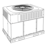
Locating the unit's model and serial number information.

Inspect Shipment

Checking for shipping damage before removing packaging.

Provide Unit Support

Instructions for securing the unit to a curb or mounting pad.

Roof Curb

Guidance on installing the roof curb and ensuring a watertight seal.

Slab Mount

Instructions for placing the unit on a concrete pad.

Field Fabricate Ductwork

Guidelines for creating and installing ductwork connections.

Provide Clearances

Specifies minimum clearances required for unit operation and servicing.

Rig and Place Unit

Safe procedures for rigging and lifting the unit into position.

Connect Condensate Drain

How to connect the condensate drain line and install a trap.

Install Flue Hood

Instructions for installing the flue hood assembly for proper venting.

Install Gas Piping

Guidelines for connecting the gas supply line to the unit.

Install Duct Connections

Connecting ductwork to the unit's supply and return openings.

Configuring Units for Downflow (Vertical) Discharge

Steps to adapt the unit for vertical downflow duct configuration.

Install Electrical Connections

Instructions for making high-voltage and control-voltage wiring connections.

Special Procedures for 208-v Operation

Specific wiring adjustments for 208-volt operation.

Control Voltage Connections

Guidelines for connecting thermostat and low-voltage wiring.

Standard Connection

Basic wiring procedures for control voltage connections.

Heat Anticipator Setting

How to properly adjust the heat anticipator on thermostats.

Transformer Protection

Information on transformer protection and fuse replacement.

Pre-Start-Up

Start-Up

Check for Refrigerant Leaks

Procedure to locate and repair refrigerant leaks.

Start-up Heating and Make Adjustments

Steps for initial heating start-up and adjustments.

Check Heating Control

Verifying proper operation of the heating control system.

Check Gas Input

Procedures for checking and adjusting the unit's gas input.

Adjust Gas Input

Detailed steps for adjusting gas input based on pressure or flow.

Measure Gas Flow (Natural Gas Units)

Method for measuring gas flow at the meter.

Measure Manifold Pressure (Propane Units)

Checking gas input via manifold pressure for propane.

Check Burner Flame

Visual inspection of burner flames for proper operation.

Connection Wiring Diagram

Ladder Wiring Diagram

Connection Wiring Diagram

Ladder Wiring Diagram

Connection Wiring Diagram

Ladder Wiring Diagram

Normal Operation

Airflow and Temperature Rise

Heating Sequence of Operation

Limit Switches

Rollout Switch

Start-up Cooling and Make Adjustments

Checking Cooling Control Operation

Verifying proper operation of the cooling control system.

Checking and Adjusting Refrigerant Charge

Method for checking and adjusting the refrigerant charge.

Indoor Airflow and Airflow Adjustments

Gas Heating Fan Speed Set-up

How to change the fan speed for gas heating operation.

Single Cooling Fan Speed Set-up (Dehumidification feature not used)

Setting cooling fan speed when dehumidification is not used.

Two Cooling Fan Speeds Set-up (Dehumidification feature used)

Setting fan speeds for cooling with dehumidification feature.

Continuous Fan Operation

How the fan operates in continuous mode.

Cooling Sequence of Operation

Maintenance

Air Filter

Importance and replacement of air filters.

Indoor Blower and Motor

Cleaning instructions for the indoor blower and motor.

Maintenance

Blower Motor and Wheel Cleaning

Detailed steps for cleaning the indoor blower motor and wheel.

Induced Draft (combustion air) Blower Assembly

Cleaning and inspection of the induced draft blower assembly.

Flue Gas Passageways

Inspecting and cleaning the flue collector box and heat exchanger.

Limit Switch

Location and function of the limit switch.

Burner Ignition

Information on the unit's direct spark ignition system.

Main Burners

Inspecting main burners for issues and adjusting if necessary.

Removal of Gas Train

Procedure for removing the gas train for servicing.

Outdoor Coil, Indoor Coil, and Condensate Drain Pan

Inspecting and cleaning coils and the condensate drain pan.

Outdoor Fan

Electrical Controls and Wiring

Refrigerant Circuit

Puron Items

Metering Device (Thermostatic Expansion Valve )

Description of the TXV metering device used in the system.

Pressure Switches

Function of pressure switches in the refrigeration circuit.

Loss of Charge Switch

Role of the loss of charge switch in system protection.

High-Pressure Switch

Copeland Scroll Compressor (Puron Refrigerant)

Refrigerant System

Compressor Oil

Servicing Systems on Roofs with Synthetic Materials

Synthetic Roof Precautionary Procedure

Liquid Line Filter Drier

Puron (R-410A) Refrigerant Charging

PuronĀ® (R-410A) Quick Reference Guide

Troubleshooting Chart

Troubleshooting Guide-Heating

Troubleshooting Guide-LED Status Codes

Start-Up Checklist

Vertical Economizer (Factory Installed Option)

General

General overview of the economizer system and its features.

Accessories

Available field-installed accessories for the economizer.

Small Chassis

Installation procedure for the vertical economizer on small chassis.

Vertical Economizer (Factory Installed Option)

Filter Part Number

Part numbers for indoor coil air filters.

Large Chassis

Filter Part Number

Part numbers for indoor coil air filters.

Configuration

Economizer Standard Sensors

Description of economizer sensors and their functions.

Low Temperature Compressor Lockout Switch

Function of the low ambient lockout switch.

Economizer Control Modes

Outdoor Dry Bulb Changeover

Setting up economizer for outdoor dry bulb changeover control.

Outdoor Enthalpy Changeover

Setting up economizer for enthalpy changeover control.

Economizer Control Modes

Differential Enthalpy Control

Setting up economizer for differential enthalpy control.

Indoor Air Quality (IAQ) Sensor Input

Connecting and configuring the IAQ sensor for ventilation.

Exhaust Set Point Adjustment

Adjusting the exhaust fan set point based on damper position.

Minimum Position Control

Setting the minimum damper position for ventilation.

Economizer Wiring Diagram

Connection Wiring Diagram

Ladder Wiring Diagram

Connection Wiring Diagram

Ladder Wiring Diagram

Demand Controlled Ventilation (DCV)

CO2 Sensor Configuration

Configuring the CO2 sensor for equipment and ventilation.

Dehumidification of Fresh Air with DCV Control

Impact of dehumidification on fresh air and DCV control.

Operation

Sequence of Operation

Step-by-step operation of the economizer control.

Troubleshooting

Economizer Preparation

Procedure to prepare the economizer for troubleshooting tests.

Differential Enthalpy

Checking differential enthalpy control operation.

Single Enthalpy

Checking single enthalpy control operation.

DCV (Demand Controlled Ventilation) and Power Exhaust

Checking DCV and power exhaust functions.

DCV Minimum and Maximum Position

Verifying minimum and maximum damper positions for DCV.

Supply-Air Input

Checking the supply-air input for the economizer.

Economizer Troubleshooting Completion

Procedure to return the economizer to normal operation.

Related product manuals