56
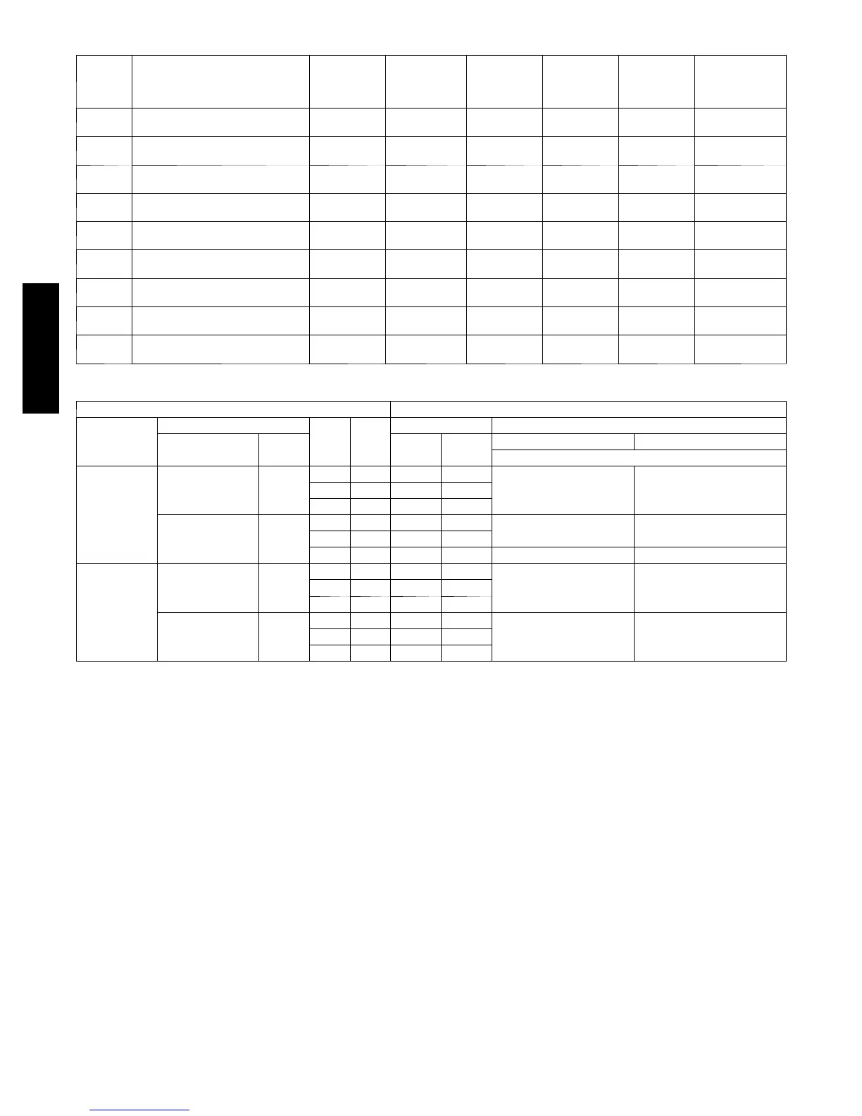
Table21–CO
2
Sensor Standard Settings
SETTING EQUIPMENT OUTPUT
VENTILATION
RA TE
(CFM/
PERSON)
ANALOG
OUTPUT
CO
2
CONTROL
RANGE
(PPM)
OPTIONAL
RELAY
SETPOINT
(PPM)
RELAY
HYSTERESIS
(PPM)
1 Proportional Any
0 --- 1 0 V
4 --- 2 0 m A
0---2000 1000 50
2
Interface w/Standard Building
Control System
Proportional Any
2 --- 1 0 V
7 --- 2 0 m A
0---2000 1000 50
3 Exponential Any
0 --- 1 0 V
4 --- 2 0 m A
0---2000 1100 50
4 Proportional 15
0 --- 1 0 V
4 --- 2 0 m A
0---1100 1100 50
5 Economizer Proportional 20
0 --- 1 0 V
4 --- 2 0 m A
0 --- 9 0 0 900 50
6 Exponential 15
0 --- 1 0 V
4 --- 2 0 m A
1---1100 1100 50
7 Exponential 20
0 --- 1 0 V
4 --- 2 0 m A
0 --- 9 0 0 900 50
8 Health & Safety Proportional ---
0 --- 1 0 V
4 --- 2 0 m A
0---9999 5000 500
9 Parking/Air Intakes/Loading Docks Proportional ---
0 --- 1 0 V
4 --- 2 0 m A
0---2000 700 50
Table22–CO
2
Sensor Standard Settings Economizer Input/Output Logic
INPUTS OUTPUTS
DEMAND
CONTROL
VENTILATION
(DCV)
ENTHALPY
Y1 Y2
COMPRESSOR NTERMINAL
OUTDOOR RETURN
STAGE
1
STAGE
2
OCCUPIED UNOCCUPIED
DAMPER
Below set (DCV
LED Off)
High (Free Cool ing
LED off)
Low
On On On On
Minimum position ClosedOn Off On Off
Off Off Off Off
Low (Free Cooling
LED on)
High
On On On Off
Modulating** (between min.
p o si t i o n a n d f u l l --- o p e n )
Modulating** (between closed
a n d f u l l --- o p e n )
On Off Off Off
Off Off Off Off Minimum position Closed
Above set (DCV
LED On)
High (Free Cool ing
LED off)
Low
On On On On
Modulating{{ (between
min. position and DC V
maximum)
Modulating{{ (between closed
and DCV maximum)
On Off On Off
Off Off Off Off
Low (Free Cooling
LED on)
High
On On On Off
Modulating*** Modulating{{{On Off Off Off
Off Off Off Off
* For single enthalpy control, the module compares outdoor enthalpy to the ABCD set point.
{Power at N terminal determines Occupied/Unoccupied setting: 24 vac (Occupied), now power (Unoccupied).
**Modulating is based on the supply--- air sensor signal.
{{Modulation is based on the DCV signal.
***Modulation is based on the greater of DCV and supply--- air sensor signals, between minimum position and either maximum position (DCV) or fully open (supply--- a ir signal).
{{{Modulating is based on the greater of DCV and supply--- air sensor signals, between closed and wither maximum position (DCV) or fully open (supply--- a ir signal).
OPERATION
Sequence of Operation—When free cooling is not available, the
compressor will be controlled by the thermostat. When free cooling
is available, the outdoor--air damper is modulated by theEconomizer
control to provide a 50_ to 55_F(10_ to 12.8_C) supply --air
temperature into the zone. As the supply --air temperature fluctuates
above 55_ (12.8_C) or below 50_F(10_C), the dampers will be
modulated (open or close) to bring the supply--air temperature back
within the set points. For Economizer operation, there must be a
thermostat call for the fan (G). This will move the damper to its
minimum position during the occupied mode.
NOTE: The DCV Max potentiometer must be colosed (CCW)
when not using CO
2
sensor.
Above 50_F(10_C) supply--air temperature, the dampers will
modulate from 100% open to the minimum open position. From
50_Fto45_F(10_ to 7.2_C) supply --air temperature, the dampers
will maintain at the minimum open position. Below 45_F(7.2_C),
the dampers will be completely shut. As the supply--air temperature
rises, the dampers will come back open to the minimum open position
once the supply--air temperature rises to 48_F(8.9_C). If power
exhaust is installed, as the outdoor-- air damper opens and closes, the
power exhaust fans will be energized and deener gized. If field--
installed accessory CO
2
sensors are connected to the Economizer
control, a demand controlled ventilation strategy will begin to
operate. As the CO
2
level in the zone increases above the CO
2
set
point, the minimum position of the damper will be increased
proportionally. As the CO
2
level decreases because of the increase in
fresh air, the outdoor--air damper will be proportionally closed.
Damper position will follow the higher demand condition from DCV
mode or free cooling mode. Damper movement from full closed to
full open (or vice versa) will take between 1 1/2 and 2 1/2 minutes.
If free cooling can be used as determined from the appropriate
changeover command (dry bulb, enthalpy curve, or differential
enthalpy), a call for cooling (Y1 closes at the thermostat) will cause
the control to modulate the dampers open to maintain the supply air
temperature set point at 50_ to 55_F(10_ to 12.8_C). As the supply
air temperature drops below the set point range of 50_ to 55_F(10_
to 12.8_C), the control will modulate the outdoor-- air dampers closed
to maintain the proper supply--air temperature.
574D-- -- A

 Loading...