10
Table 2 – Maximum Gas Flow Capacity*
NOMINAL
IRON PIPE
SIZE (IN.)
INTERNAL
DIAMETER
(IN.)
LENGTH OF PIPE FT (m)†
10
(3)
20
(6)
30
(9)
40
(12)
50
(15)
60
(18)
70
(21)
80
(24)
90
(27)
100
(30)
125
(38)
150
(46)
175
(53)
200
(61)
1/2 .622 175 120 97 82 73 66 61 57 53 50 44 40 — —
3/4 .824 360 250 200 170 151 138 125 118 110 103 93 84 77 72
1 1.049 680 465 375 320 285 260 240 220 205 195 175 160 145 135
1 --- 1 / 4 1.380 1400 950 770 600 580 530 490 460 430 400 360 325 300 280
1 --- 1 / 2 1.610 2100 1460 1180 990 900 810 750 690 650 620 550 500 460 430
*Capacity of pipe in cu ft of gas per hr for gas pressure of 0.5 psig or less. Pressure drop of 0.5 ---IN. W.C. (based on a 0.60 specific gravity gas). Refer to Table
2 and National Fuel Gas Code NFPA 54/ANSI Z223.1.
{ This length includes an ordinary number of fittings.
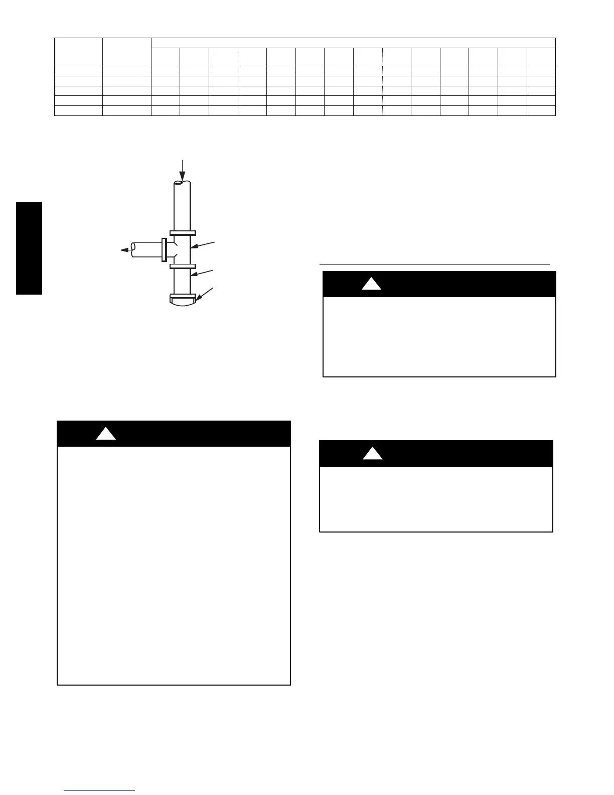
OUT
TEE
NIPPLE
CAP
IN
C99020
Fig. 8 -- Sediment Trap
NOTE: Pressure test the gas supply system after the gas supply
piping is connected to the gas valve. The supply piping must be
disconnected from the gas valve during the testing of the piping
systems when test pressure is in excess of 0.5 psig. Pressure test the
gas supply piping system at pressures equal to or less than 0.5 psig.
The unit heating section must be isolated from the gas piping
system by closing the external main manual shutoff valve and
slightly opening the ground--joint union.
FIRE OR EXPLOSION HAZARD
Failure to follow this warning could result in personal injury,
death and/or property damage.
--Connect gas pipe to unit using a backup wrench to avoid
damaging gas controls.
--Never purge a gas line into a combustion chamber. Never
test for gas leaks with an open flame. Use a commercially
available soap solution made specifically for the detection of
leaks to check all connections.
--Use proper length of pipe to avoid stress on gas control
manifold.
--If a flexible connector is required or allowed by authority
having jurisdiction, black iron pipe shall be installed at
furnace gas valve and extend a minimum of 2 in. (51 mm)
outside furnace casing.
--If codes allow a flexible connector, always use a new
connector. do not use a connector which has previously
serviced another gas appliance.
!
WARNING
8. Check for gas leaks at the field--installed and
factory--installed gas lines after all piping connections have
been completed. Use a commercially available soap solution
(or method specified by local codes and/or regulations).
Step 9 — Install Duct Connections
The unit has duct flanges on the supply-- and return--air openings
on the side and bottom of the unit. For downshot applications, the
ductwork connects to the roof curb (See Fig. 2 and 3 for
connection sizes and locations).
Configuring Units for Downflow (Vertical) Discharge
ELECTRICAL SHOCK HAZARD
Failure to follow this warning could result in personal
injury or death.
Before installing or servicing system, always turn of f main
power to system and install lockout tag. There may be
more than one disconnect switch.
!
WARNING
1. Open all electrical disconnects before starting any service
work.
2. Remove horizontal (metal) duct covers to access vertical
(downflow) discharge duct knockouts in unit basepan.
PROPERTY DAMAGE HAZARD
Failure to follow this caution may result in property damage.
Collect ALL screws that were removed. Do not leave screws
on rooftop as permanent damage to the roof may occur.
CAUTION
!
To remove downflow return and supply knockout covers, break
front and right side connections tabs with a screwdriver and
hammer . Push cover down to break rear and left side tabs.
NOTE: These panels are held in place with tabs similar to an
electrical knockout. Reinstall horizontal duct covers (Fig. 9)
shipped on unit from factory. Insure openings are air and
watertight.
NOTE: The design and installation of the duct system must be in
accordance with the standards of the NFPA for installation of
nonresidence--type air conditioning and ventilating systems, NFPA
90A or residence--type, NFPA 90B; and/or local codes and
ordinances.
574D-- -- A

 Loading...