3
Wiring Considerations
Ordinary thermostat wire is recommended. Use 22 AWG or larger
for normal wiring applications. Continuous wire lengths over
100--ft. (3 m) should use 20 AWG or larger.
NOTE: ABCD bus wiring only requires a four-- wire connection;
however, it is good practice to run thermostat cable having more
than four wires in the event of a damaged or broken wire during
installation.
Each communicating device in the Evolution Zone System has a
four--pin connector labeled ABCD. It is recommended that the
following color code be used when wiring each device:
A — Green = Data A
B — Yellow = Data B
C — White = 24VAC (Com)
D — Red = 24VAC (Hot)
It is not mandatory that the above color code be used, but each
ABCD connector in the system MUST be wired consistently.
Shielded Wire
If the thermostat wiring will be located near or in parallel with high
voltage wiring, cable TV, Ethernet wiring, or radio frequency
equipment, then shielded thermostat wire can be used to reduce or
eliminate potential interference. The shield wire should be
connected to the C terminal, or ground, at the indoor unit. The
shield wire should NOT be connected to any terminal at the user
interface. Connecting the shield to ground at both ends can cause
current loops in the shield, reducing shield effectiveness.
Locating Damper Control Module
All wiring is run back to the Damper Control Module. Select a
location near the furnace or fan coil where wiring from the User
Interface, each Remote Room Sensor or Smart Sensor, each
damper actuator , and the equipment itself can come together easily.
The Damper Control Module is approved for indoor use only and
should never be installed with any of its components exposed to
the elements. The Damper Control Module (and zone dampers)
may be installed in any area where the temperature remains
between --4_F to 158_F(--20_Cto70_C), and there is no
condensation. The cover must be installed to prevent damage from
other sources. Do not locate where it will be accessible to children.
It may be mounted in either vertical or horizontal position.
Remember that wiring access is likely the most important
consideration.
ELECTRICAL OPERATION HAZARD
Failure to follow this caution may result in equipment damage
or improper operation.
To prevent possible damage to the Damper Control Module,
DO NOT mount on plenum, ductwork, or flush against
furnace or fan coil.
CAUTION
!
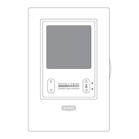
Mounting Evolution Zone Control
First, become familiar with all plastic assembly pieces shown in
Figures 3 through 6. The User Interface will snap together with the
backplate.
A
D
S1
C
B
S2
A09441
Fig. 3 -- Backplate
A backplate is supplied (See Fig. 4). Attach backplate to the wall
using only a small hole in the wall allowing a four wire connection
to pass through. Mount the assembly to the backplate.
A09486
Fig. 4 -- Evolutiont Zone Control
NOTE: Once Evolution Zone Control is secured to wall with the
backplate assembly (snapped together), care must be taken not to
bend or break the interlocking tabs when removing.
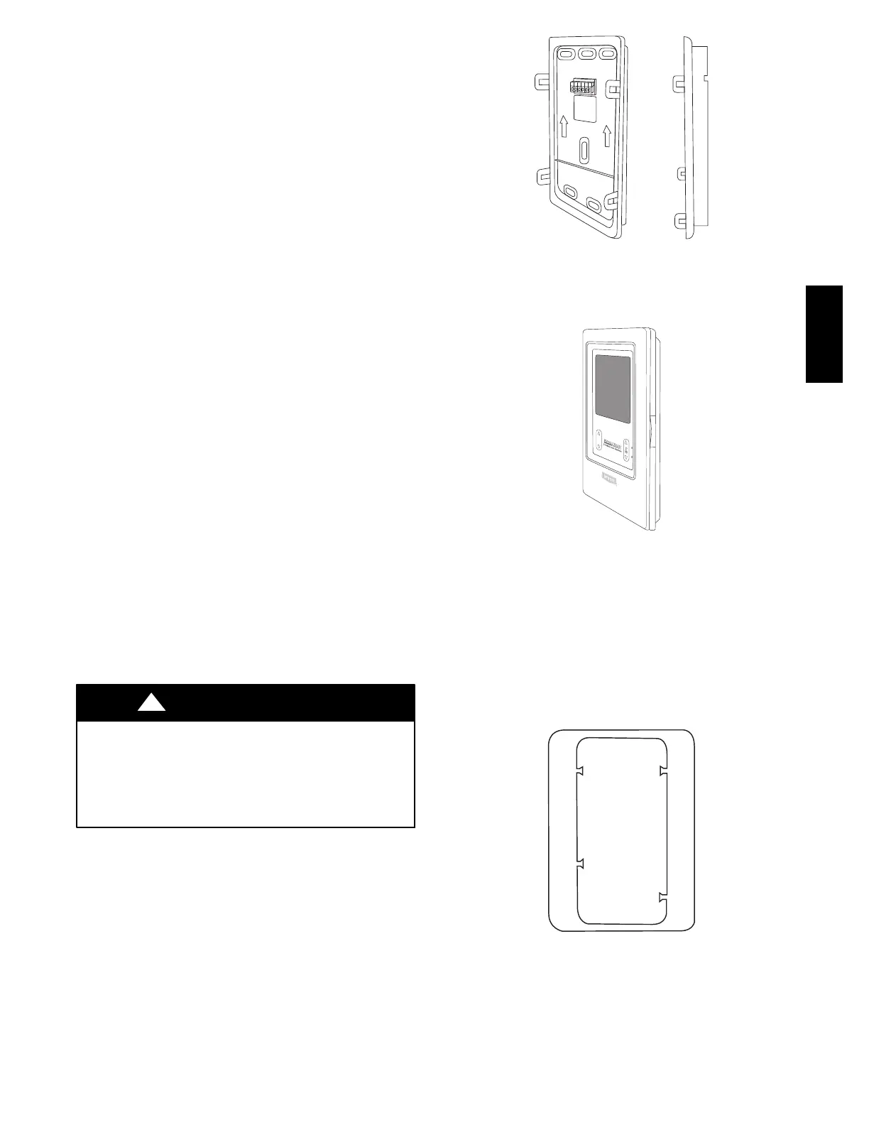
Decorative Backplate
Sold separately, a thin decorative backplate (see Fig. 5) is available
to hide any marks/screw holes left from the previous thermostat.
This decorative backplate (or beauty ring) is used by snapping it
onto the back of the mounting plate before securing the plate to the
wall.
A04017
Fig. 5 -- Decorative Backplate
UIZ01-- D
 Loading...