3
Table 1 – Accessory Usage
Accessory
REQUIRED FOR LOW---AMBIENT
COOLING APPLICATIONS
(Below 55°F / 12.8°C)
REQUIRED FOR
LONG LINE APPLICATIONS*
REQUIRED FOR
SEA COAST APPLICATIONS
(Within 2 miles / 3.22 km)
Accumulator Standard Standard Standard
Ball Bearing Fan Motor Ye s{ No No
Compressor Start Assist Capacitor and
Relay
Ye s Ye s No
Crankcase Heater Ye s
Ye s
No
Evaporator Freeze Thermostat Ye s No No
Hard Shutoff TXV Ye s Ye s Ye s
Isolation Relay Yes No No
Liquid Line Solenoid Valve No See Long---Line Application Guideline No
Motor Master® Control or
Low Ambient Switch
Ye s No No
Support Feet Recommended No Recommended
* For tubing line sets between 80 and 200 ft. (24.38 and 60.96 m) and/or 20 ft. (6.09 m) vertical differential, ref er to Residential Split---System L o ngline
Application Guideline.
{ Additional requirement for Low ---Ambient Controller (full modulation feature) MotorMasterr Control.
Always Ask For
Outdoor Unit Connected To Factory Approved Indoor
Unit
Outdoor unit contains approximate system refrigerant charge for
operation with approved AHRI rated indoor unit when connected
by 15 ft (4.57 m) of field--supplied or factory--accessory tubing,
and factory supplied filter drier. Some indoor units require
additional subcooling to achieve optimal heating performance.
Using Tables 5 or 6– Additional Subcooling Required, check
refrigerant charge for maximum efficiency
Refrigerant Tubing and Sweat Connections
Connect vapor tube to fitting on outdoor unit vapor service valves
(see Table 2). Connect liquid tubing to adapter tube on liquid
service valve. Use refrigerant grade tubing.
CAUTION
!
UNIT DAMAGE HAZARD
Failure to follow this caution may result in equipment
damage or improper operation.
Service valves must be wrapped in a heat--sinking material
such as a wet cloth while brazing.
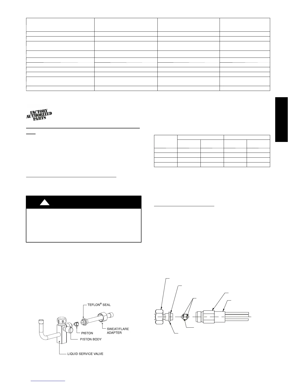
Remove plastic retainer holding outdoor piston in liquid service
valve, leaving the piston and piston retainer inside the valve.
Connect sweat/flare adapter provided, to valve. (See Fig. 4.)
Connect refrigerant tubing to fittings on outdoor unit vapor and
liquid service valves. Service valves are closed from factory and
ready for brazing. After wrapping service valve with a wet cloth,
tubing set can be brazed to service valve using either silver bearing
or non--silver bearing brazing material. Do not use soft solder
(materials which melt below 800°F/427°C). Consult local code
requirements. Refrigerant tubing and indoor coil are now ready for
leak testing. This check should include all field and factory joints.
A05226
Fig. 4 -- Liquid Service Valve
Table 2 – Refrigerant Connections and Recommended Liquid
and Vapor Tube Diameters (In.)
UNIT SIZE
LIQUID RATED VAPOR
Connection
Diameter
Tube
Diameter
Connection
Diameter
Tube
Diameter
018, 024 3/8 3/8 5/8 5/8
030, 036 3/8 3/8 3/4 3/4
042, 048 3/8 3/8 7/8 7/8
060 3/8 3/8 7/8 1--1/8
* Units are rated with 25 ft. (7.6 m) of lineset. See Product Data sheet for performance
data when using different size and length linesets.
Notes:
1. Do not apply capilla ry tube indoor coils to these units.
2. For Tubing Set lengths between 80 and 200 ft. (24.38 and 60.96 m) horizontal or
20 ft. (6.09 m) vertical differential 250 ft. (76.2 m) Total Equivalent Length, refer to
the Residential Piping and Longline Guideline --- Air Co nditio ners and Hea t Pumps
using Puron refrigerant.
Installing with Indoor Piston
Outdoor Unit Connected to Factory Approved Indoor Unit
Check piston size shipped with indoor unit to see if it matches
required indoor piston size. If it does not match, replace indoor
piston with correct piston size.
NOTE: Correct pistons are shipped with outdoor units in the
accessory bag and are only qualified for piston fan coils. Example
fan coils with piston: FB4C and FY5B (1.5 through 4 ton)
When changing indoor piston, use a back−up wrench. Hand
tighten hex nut, then tighten with wrench 1/2 turn. Do not exceed
30 ft−lbs. The indoor piston contains a Teflon ring (or seal) which
is used to seat against the inside of distributor body, and must be
installed properly to ensure proper seating. See Fig. 5.
13/16” BRASS HEX NUT
TEFLON® SEAL
TEFLON®
RINGS
3/4” BRASS HEX BOD
“H” DISTRIBUTOR
PISTON RETAINER
PISTON
A10342
Fig. 5 -- Indoor Piston Installation
213B / 215B

 Loading...