EasyManua.ls Logo

Bryant Legacy 215B User Manual

Bryant Legacy 215B
12 pages
To Next Page IconTo Next Page
Page #1 background imageLoading...
Page #1 background image
213B, 215B
Legacyt Line Heat Pump
with Puronr Refrigerant
1--1/2 To 5 Nominal Tons
Installation Instructions
NOTE: Read the entire instruction manual before starting the
installation.
SAFETY CONSIDERATIONS
Improper installation, adjustment, alteration, service, maintenance,
or use can cause explosion, fire, electrical shock, or other
conditions which may cause death, personal injury, or property
damage. Consult a qualified installer, service agency, or your
distributor or branch for information or assistance. The qualified
installer or agency must use factory--authorized kits or accessories
when modifying this product. Refer to the individual instructions
packaged with the kits or accessories when installing.
Follow all safety codes. Wear safety glasses, protective clothing,
and work gloves. Use quenching cloth for brazing operations.
Have fire extinguisher available. Read these instructions
thoroughly and follow all warnings or cautions included in
literature and attached to the unit. Consult local building codes and
current editions of the National Electrical Code (NEC) NFPA 70.
In Canada, refer to current editions of the Canadian electrical code
CSA 22.1.
Recognize safety information. This is the safety--alert symbol
!
!
.
When you see this symbol on the unit and in instructions or
manuals, be alert to the potential for personal injury.
Understand these signal words; DANGER, WARNING, and
CAUTION. These words are used with the safety--alert symbol.
DANGER identifies the most serious hazards which will result in
severe personal injury or death. WARNING signifies hazards
which could result in personal injury or death. CAUTION is used
to identify unsafe practices which may result in minor personal
injury or product and property damage. NOTE is used to highlight
suggestions which will result in enhanced installation, reliability, or
operation.
!
WARNING
ELECTRICAL SHOCK HAZARD
Failure to follow this warning could result in personal injury
or death.
Before installing, modifying, or servicing system, main
electrical disconnect switch must be in the OFF position.
There may be more than 1 disconnect switch. Lock out and
tag switch with a suitable warning label.
CUT HAZARD
Failure to follow this caution may result in personal injury.
Sheet metal parts may have sharp edges or burrs. Use care and
wear appropriate protective clothing and gloves when handling
parts.
CAUTION
!
INSTALLATION RECOMMENDATIONS
NOTE: In some cases noise in the living area has been traced to
gas pulsations from improper installation of equipment.
1. Locate unit away from windows, patios, decks, etc. where
unit operation sound may disturb customer.
2. Ensure that vapor and liquid tube diameters are appropriate
for unit capacity.
3. Run refrigerant tubes as directly as possible by avoiding un-
necessary turns and bends.
4. Leave some slack between structure and unit to absorb vi-
bration.
5. When passing refrigerant tubes through the wall, seal open-
ing with RTV or other pliable silicon--based caulk (see Fig.
1).
6. Avoid direct tubing contact with water pipes, duct work,
floor joists, wall studs, floors, and walls.
7. Do not suspend refrigerant tubing from joists and studs with
a rigid wire or strap which comes in direct contact with
tubing (see Fig. 1).
8. Ensure that tubing insulation is pliable and completely sur-
rounds vapor tube.
9. When necessary, use hanger straps which are 1 in. wide and
conform to shape of tubing insulation (see Fig. 1).
10. Isolate hanger straps from insulation by using metal sleeves
bent to conform to shape of insulation.
INSULATION
SUCTION TUBE
LIQUID TUBE
OUTDOOR WALL INDOOR WALL
LIQUID TUBE
SUCTION TUBE
INSULATION
CAULK
HANGER STRAP
(AROUND SUCTION
TUBE ONLY)
JOIST
1” (25.4 mm)
MIN
THROUGH THE WALL
SUSPENSION
A07588
Fig. 1 -- Connecting Tubing Installation
When outdoor unit is connected to factory--approved indoor unit,
outdoor unit contains system refrigerant charge for operation with
AHRI rated indoor unit when connected by 15 ft. (4.57 m) of
field--supplied or factory accessory tubing. For proper unit
operation, check refrigerant charge using charging information
located on control box cover and/or in the Check Charge section of
this instruction.
IMPORTANT: Maximum liquid--line size is 3/8--in. OD for all
residential applications including long line.
IMPORTANT: Always install the factory--supplied liquid--line
filter drier. Obtain replacement filter driers from your distributor or
branch.

Other manuals for Bryant Legacy 215B

Question and Answer IconNeed help?

Do you have a question about the Bryant Legacy 215B and is the answer not in the manual?

Bryant Legacy 215B Specifications

General IconGeneral
TypeHeat Pump
SEER RatingUp to 15
HSPF RatingUp to 8.5
RefrigerantR-410A
Number of Stages1
Compressor TypeSingle Stage
Warranty10-year parts limited warranty

Summary

Safety Considerations

Electrical Shock Hazard

Warning about potential electrical shock during installation or servicing and steps to prevent it.

Cut Hazard

Caution regarding sharp edges on sheet metal parts and necessary precautions.

Installation Recommendations

Installation

Check Equipment and Job Site

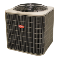
Steps for unpacking, inspecting unit, and checking rating plate for installation.

Install on a Solid, Level Mounting Pad

Instructions for securing the unit to a level mounting pad and hurricane tie-downs.

Clearance Requirements

Specifies minimum clearances needed around the unit for airflow, service, and placement.

Operating Ambient

Details acceptable outdoor temperature ranges for cooling and heating modes.

Check Defrost Thermostat

Procedure to verify the defrost thermostat is properly located and securely attached.

Make Piping Connections

Guidance on connecting refrigerant tubing to service valves, avoiding bends and contact.

Outdoor Unit Connected To Factory Approved Indoor Unit

Information on connecting the outdoor unit to compatible indoor units and subcooling requirements.

Refrigerant Tubing and Sweat Connections

Instructions for making refrigerant tubing connections using sweat or flare fittings.

Installing with Indoor Piston

Steps for installing or replacing the indoor piston for correct system operation.

Install Liquid Line Filter Drier Indoor

Procedure for installing the liquid line filter drier inside the unit.

Evacuate Refrigerant Tubing and Indoor Coil

Instructions for evacuating the system to 500 microns using the deep vacuum method.

Final Tubing Check

Important checks to ensure tubing is not rubbing and wiring is secure.

Make Electrical Connections

Guidelines for wiring, including compliance with codes and proper connections.

Connect Control Wiring

Instructions for routing and connecting 24v control wires to the unit.

Final Wiring Check

Ensuring all factory and field wire connections are secured properly.

Compressor Crankcase Heater

Requirement to furnish power to the crankcase heater before starting the unit.

Install Electrical Accessories

Refer to individual instructions for installing kits or accessories.

Start-Up

Steps to properly start up the system after installation, including thermostat settings.

Sequence of Operation

Detailed explanation of system operation in cooling, heating, and defrost modes.

Defrost

Explanation of the time/temperature defrost control and initiation procedure.

Check Charge

Procedures for checking and adjusting system refrigerant charge using subcooling or superheat.

Units with Cooling Mode TXV

Specific charging method (subcooling) for units with cooling mode TXV.

Units with Indoor Pistons

Specific charging method (superheat) for units with indoor pistons.

Heating Check Chart Procedure

Guidance on using the heating check chart to verify system refrigerant charge.

Final Checks

Essential checks to perform before leaving the job site for proper installation.

Related product manuals