Do you have a question about the Bryant Legacy 213B and is the answer not in the manual?
Important safety information, signal words (DANGER, WARNING, CAUTION), and personal injury prevention.
Warning about electrical shock hazard and the need to disconnect power before installation.
Warning about personal injury and environmental hazards during piping, and instructions for refrigerant tubing.
Instructions for evacuating the system using the deep vacuum method to remove air and moisture.
Safety warnings and instructions for connecting power and ground wires to the unit.
Safety warnings and a step-by-step procedure for starting up the system after installation.
Procedures for checking and adjusting refrigerant charge using subcooling or superheat methods based on conditions.
Detailed steps for checking refrigerant charge using the subcooling method for TXV systems.
Detailed steps for checking refrigerant charge using the superheat method for piston systems.
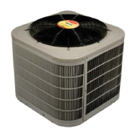
This document provides installation and maintenance instructions for the Bryant Legacy™ Line Heat Pump, models 213B and 215B, with Puron® Refrigerant, ranging from 1-1/2 to 5 nominal tons. It emphasizes safety considerations, installation recommendations, piping connections, electrical connections, start-up procedures, and charging methods for optimal performance.
The Bryant Legacy™ Line Heat Pump is designed to provide both heating and cooling for residential and light commercial applications. It utilizes Puron® (R-410A) refrigerant, which operates at higher pressures than R-22, necessitating specific servicing equipment and components. The unit is designed for connection to a factory-approved indoor unit, forming a complete split system. Its operation involves a sophisticated control system that manages refrigerant flow, fan motor operation, and defrost cycles to maintain desired indoor temperatures efficiently. The heat pump can operate in cooling mode with a minimum outdoor ambient of 55°F (12.78°C) and a maximum of 125°F (51.67°C), and in heating mode with a maximum outdoor ambient of 66°F (18.89°C). The defrost control is a time/temperature-based system, factory-set to 90 minutes, with field-selectable options for 30 or 60 minutes. This control ensures efficient defrosting of the outdoor coil during heating operation to prevent ice buildup and maintain performance.
The installation process begins with unpacking and inspecting the unit for any shipping damage. It must be installed on a solid, level mounting pad, with provisions for tie-down bolts if required by local codes. For rooftop applications, the unit should be placed on a level platform or frame, above a load-bearing wall, and isolated from the structure to minimize vibration transmission. Adequate clearances are crucial for proper airflow, wiring, refrigerant piping, and service access. A minimum of 24 inches (609.6 mm) is required at the service end, 48 inches (1219.2 mm) above the unit, 6 inches (152.4 mm) on one side, and 12 inches (304.8 mm) on all remaining sides. For units with wire grille coil guards, an 18-inch (457.2 mm) clearance between units is acceptable if there is no overhang within 12 feet (3.66 m). Units with louver panels require 24 inches (609.6 mm) between units.
Refrigerant tubing connections are critical for system integrity and performance. The document provides detailed instructions for connecting vapor and liquid tubes, emphasizing the use of refrigerant-grade tubing and proper brazing techniques. Service valves must be wrapped in a heat-sinking material, such as a wet cloth, during brazing to prevent damage. The unit is shipped with a factory charge for operation with 15 feet (4.57 m) of tubing. For optimal performance, the refrigerant charge needs to be checked and adjusted based on the specific indoor unit and tubing length. The document outlines two primary charging methods: the subcooling method for units with a TXV (Thermostatic Expansion Valve) and the superheat method for units with indoor pistons. Favorable conditions for charging exist when the outdoor temperature is between 70°F (21.11°C) and 100°F (37.78°C), and the indoor temperature is between 70°F (21.11°C) and 80°F (26.67°C).
Electrical connections must comply with local and national codes, including the National Electrical Code (NEC) NFPA 70 and the Canadian electrical code CSA 22.1. Copper wire only should be used between the disconnect switch and the unit. A branch circuit disconnect of adequate size is required and must be located within sight and readily accessible from the unit. The unit cabinet must be properly grounded to minimize personal injury in case of an electrical fault. For 3-phase units, a 3-phase monitor control ensures correct phase rotation, indicated by LED lights. Control wiring uses 18 AWG color-coded, insulated wire, with 16 AWG recommended for thermostat distances over 100 feet (30.5 m) to prevent excessive voltage drop.
Start-up procedures include fully opening liquid and vapor service valves, replacing stem caps, and energizing the system. The thermostat should be set to the desired temperature and mode (HEAT or COOL, with fan ON or AUTO) for at least 15 minutes to allow the system to stabilize before checking the refrigerant charge. If equipped, the crankcase heater must be powered for a minimum of 24 hours before starting the unit to prevent compressor damage.
The manual stresses the importance of regular maintenance for continuing high performance and minimizing equipment failure. This includes periodic checks of wiring and tubing to ensure they are secure and not rubbing against other components or sharp edges. All panels and covers must be securely fastened. Service valve stem caps should be tightened to 1/12-turn past finger tight. The owner's manual, which includes periodic maintenance requirements, should be left with the customer, and a Dealer Installation Checklist should be completed and filed.
For systems requiring service, federal regulations mandate that refrigerant not be vented to the atmosphere. Recovery of refrigerant is required during system repair or final unit disposal. If the system is opened for service, refrigerant must be recovered, the system evacuated to 500 microns, and filter driers replaced. The deep vacuum method, pulling a vacuum of 500 microns, is recommended to ensure the system is free of air and liquid water. A tight, dry system will hold a vacuum of 1000 microns for approximately 7 minutes. The factory-supplied liquid-line filter drier must always be installed, and replacement driers should be obtained from an authorized distributor. Puron® (R-410A) systems require specific filter driers designed for higher working pressures (at least 600 psig) and should not use R-22 TXVs or capillary tube coils. All indoor coils must be installed with a hard shutoff Puron TXV metering device. POE oils, used with Puron, absorb moisture rapidly and should not be exposed to the atmosphere. They can also damage certain plastics and roofing materials, so care must be taken during handling.
| Refrigerant | R-410A |
|---|---|
| Stages | Single stage |
| Voltage | 208/230 V |
| SEER | up to 16 |
| HSPF | up to 9.0 |
| Number of Stages | 1 |
| Efficiency | Up to 16 SEER |
| Sound Level | 72 dB |
| Sound Level (Outdoor Unit) (dB) | 72 |