EasyManua.ls Logo

Bryant 661C User Manual

Bryant 661C
8 pages
To Next Page IconTo Next Page
Page #1 background imageLoading...
Page #1 background image
NOTE: Read the entire instruction manual before starting the
installation.
SAFETY CONSIDERATIONS
Improper installation, adjustment, alteration, service, maintenance,
or use can cause explosion, fire, electrical shock, or other
conditions which may cause death, personal injury, or property
damage. Consult a qualified installer, service agency, or your
distributor or branch for information or assistance. The qualified
installer or agency must use factory-authorized kits or accessories
when modifying this product. Refer to the individual instructions
packaged with the kits or accessories when installing.
Follow all safety codes. Wear safety glasses, protective clothing,
and work gloves. Use quenching cloth for brazing operations.
Have fire extinguisher available. Read these instructions thor-
oughly and follow all warnings or cautions included in literature
and attached to the unit. Consult local building codes and National
Electrical Code (NEC) for special requirements.
Recognize safety information. This is the safety-alert symbol
.
When you see this symbol on the unit and in instructions or
manuals, be alert to the potential for personal injury.
Understand the signal words DANGER, WARNING, and CAU-
TION. These words are used with the safety-alert symbol. DAN-
GER identifies the most serious hazards which will result in severe
personal injury or death. WARNING signifies hazards which
could result in personal injury or death. CAUTION is used to
identify unsafe practices which would result in minor personal
injury or product and property damage. NOTE is used to highlight
suggestions which will result in enhanced installation, reliability,
or operation.
WARNING: Before installing, modifying, or servicing
system, main electrical disconnect switch must be in the
OFF position. There may be more than 1 disconnect
switch. Lock out and tag switch(es) with a suitable
warning label. Electrical shock can cause personal injury
or death.
INSTALLATION RECOMMENDATIONS
NOTE: In some cases noise in the living area has been traced to
gas pulsations from improper installation of equipment.
1. Locate unit away from windows, patios, decks, etc. where
unit operation sounds may disturb customer.
2. Ensure that vapor and liquid tube diameters are appropriate
to capacity of unit.
3. Run refrigerant tubes as directly as possible by avoiding
unnecessary turns and bends.
4. Leave some slack between structure and unit to absorb
vibration.
5. When passing refrigerant tubes through the wall, seal
opening with RTV or other pliable silicon-based caulk. (See
Fig. 3.)
6. Avoid direct tubing contact with water pipes, duct work,
floor joists, wall studs, floors, and walls.
7. Do not suspend refrigerant tubing from joists and studs with
a rigid wire or strap which comes in direct contact with
tubing. (See Fig. 3.)
8. Ensure that tubing insulation is pliable and completely
surrounds vapor tube.
9. When necessary, use hanger straps which are 1 in. wide and
conform to shape of tubing insulation. (See Fig. 3.)
10. Isolate hanger straps from insulation by using metal sleeves
bent to conform to shape of insulation.
Fig. 1—Models 661C
A94355
Fig. 2—Models 661G and 661S
A98524
installation and
start-up instructions
10 SEER
SPLIT-SYSTEM
HEAT PUMP
Cancels: II 661C-18-6 II 661C-18-7
2-02
661C, G
661S
—1—
Question and Answer IconNeed help?

Do you have a question about the Bryant 661C and is the answer not in the manual?

Bryant 661C Specifications

General IconGeneral
Model661C
TypeHeat Pump
SEER Rating16
HSPF Rating9.0
RefrigerantR-410A
Stages1
Voltage208/230V
Compressor TypeSingle Stage
Warranty10-year parts limited warranty upon registration

Summary

Safety and General Information

General Safety Information

Explains signal words DANGER, WARNING, CAUTION and the safety-alert symbol for injury awareness.

Electrical Safety Warning

Warning about ensuring the main electrical disconnect switch is OFF before servicing to prevent shock.

Unit Placement and Tubing Guidelines

Recommendations for unit placement and refrigerant tubing routing to minimize noise and vibration.

Installation Procedures

I. CHECK EQUIPMENT AND JOB SITE

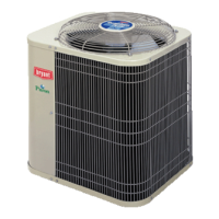
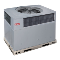
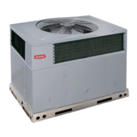
Unpack unit, inspect equipment, and check rating plate for job specifications.

II. INSTALL ON A SOLID, LEVEL MOUNTING PAD

Ensure the unit is installed on a solid, level mounting pad, within ± 2° tolerance.

III. CLEARANCE REQUIREMENTS

Maintain adequate space for airflow, wiring, piping, and service access around the unit.

IV. OPERATING AMBIENTS

Specifies minimum and maximum outdoor operating ambients for cooling and heating modes.

V. ELEVATE UNIT

Elevate unit for proper drainage in areas prone to freezing temperatures or snowfall.

VI. CHECK INDOOR AND OUTDOOR CHECK-FLO-RATER® PISTON

Verify indoor coil piston matches outdoor unit rating plate; replace if mismatch occurs.

VII. CHECK DEFROST THERMOSTAT

Ensure defrost thermostat is correctly located and securely attached to the feeder tube stub.

VIII. MAKE PIPING CONNECTIONS

Connect refrigerant tubing to service valves, use brazing shield, and perform leak testing.

IX. MAKE ELECTRICAL CONNECTIONS

Connect ground, power, and control wiring per NEC and unit specifications, checking all terminations.

X. COMPRESSOR CRANKCASE HEATER

Power the crankcase heater 24 hours before starting if refrigerant tubing exceeds 50 ft.

XII. INSTALL ELECTRICAL ACCESSORIES

Follow instructions provided with kits or accessories for proper installation.

XIII. START-UP

Procedures for starting the unit, with cautions against overcharging, vacuum, or disabling safety switches.

System Operation and Checks

DEFROST

Explains the defrost control, its time/temperature settings, and sequence of operation.

Sequence of Operation I. Cooling

Describes the cooling cycle sequence, detailing thermostat calls and component activation.

XIV. CHECK CHARGE

How to check refrigerant charge in cooling and heating modes using charts and unit rating plates.

CARE AND MAINTENANCE

Importance of periodic maintenance for continued high performance and minimizing equipment failure.

Related product manuals