EasyManua.ls Logo

Bryant 602A Series User Manual

Bryant 602A Series
26 pages
To Next Page IconTo Next Page
Page #1 background imageLoading...
Page #1 background image
NOTE: Read the entire instruction manual before starting the
installation.
TABLE OF CONTENTS
SAFETY CONSIDERATIONS .....................................................1
INTRODUCTION ..........................................................................2
RECEIVING AND INSTALLATION ..........................................2
Check Equipment......................................................................2
IDENTIFY UNIT ................................................................2
INSPECT SHIPMENT ........................................................2
Provide Unit Support ................................................................2
ROOF CURB.......................................................................2
SLAB MOUNT ...................................................................2
GROUND MOUNT ............................................................2
Provide Clearances....................................................................2
Rig and Place Unit....................................................................2
INSPECTION ......................................................................2
INSTALLATION ................................................................2
Select and Install Ductwork .....................................................5
CONVERTING HORIZONTAL DISCHARGE UNITS TO
DOWNFLOW (VERTICAL) DISCHARGE UNITS.........7
Provide for Condensate Disposal .............................................7
Install Electrical Connections...................................................7
HIGH-VOLTAGE CONNECTIONS..................................9
ROUTING POWER LEADS INTO UNIT ......................14
CONNECTING GROUND LEAD TO GROUND LUG.14
ROUTING CONTROL POWER WIRES (24-V) ............14
SPECIAL PROCEDURES FOR 208-V OPERATION ...14
PRE-START-UP ..........................................................................15
START-UP ...................................................................................15
Check for Refrigerant Leaks ..................................................15
Start-Up Adjustments..............................................................15
CHECKING COOLING AND HEATING
CONTROL OPERATION.................................................15
CHECKING AND ADJUSTING REFRIGERANT
CHARGE ...........................................................................16
REFRIGERANT CHARGE ..............................................16
NO CHARGE....................................................................16
LOW CHARGE COOLING .............................................17
TO USE COOLING CHARGING CHARTS ..................17
INDOOR AIRFLOW AND AIRFLOW ADJUST-
MENTS..............................................................................17
MAINTENANCE.........................................................................18
Air Filter..................................................................................18
Indoor blower and motor........................................................18
OUTDOOR COIL, INDOOR COIL, AND
CONDENSATE DRAIN PAN...............................................19
Outdoor fan .............................................................................19
Electrical controls and wiring ................................................20
Refrigerant circuit ...................................................................20
Indoor airflow .........................................................................20
Metering device ......................................................................20
Liquid line strainers ................................................................22
High Flow Valves...................................................................22
Time-delay relay .....................................................................22
Loss of charge switch.............................................................22
Check defrost thermostat ........................................................22
Defrost Thermostat .................................................................22
TROUBLESHOOTING ...............................................................22
START-UP CHECKLIST............................................................22
NOTE TO INSTALLER READ THESE INSTRUCTIONS
CAREFULLY AND COMPLETELY before installing this unit.
Also, make sure the Owner’s Manual and Service Instructions are
left with the unit after installation.
SAFETY CONSIDERATIONS
Installation and servicing of air-conditioning equipment can be
hazardous due to system pressure and electrical components. Only
trained and qualified personnel should install, repair, or service
air-conditioning equipment.
Untrained personnel can perform basic maintenance functions of
cleaning coils and filters. All other operations should be performed
by trained service personnel. When working on air-conditioning
equipment, observe precautions in the literature, tags, and labels
attached to the unit, and other safety precautions that may apply.
Follow all safety codes. Wear safety glasses and work gloves. Use
quenching cloth for unbrazing operations. Have fire extinguisher
available for all brazing operations.
Fig. 1—Model 601A/602A
C99001
installation, start-up,
and service instructions
3-PHASE SINGLE-PACKAGED HEAT PUMPS
Cancels: New II 601A-30-1
2-06
601A
602A
030-060
—1—
Question and Answer IconNeed help?

Do you have a question about the Bryant 602A Series and is the answer not in the manual?

Bryant 602A Series Specifications

General IconGeneral
BrandBryant
Model602A Series
CategoryHeat Pump
LanguageEnglish

Summary

SAFETY CONSIDERATIONS

General Safety Precautions

Summarizes warnings, safety alerts, and personal protective equipment requirements.

INTRODUCTION

Unit Overview and Design

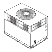
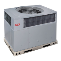
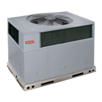
Describes the heat pump's purpose and configuration for outdoor installation.

RECEIVING AND INSTALLATION

Unit Identification and Inspection

Covers checking model number, serial number, and shipment condition upon arrival.

Unit Support and Placement

Discusses roof curb, slab, and ground mounting options for unit installation.

Providing Necessary Clearances

Details required space for airflow and service access around the unit.

Rigging and Handling Procedures

Outlines safe lifting and moving methods, emphasizing trained personnel.

SELECT AND INSTALL DUCTWORK

Ductwork Design and Installation Standards

Covers compliance with NFPA, ASHRAE standards for duct system design.

Ductwork Installation Best Practices

Includes using flexible connectors and fireproof materials for vibration isolation.

CONVERTING HORIZONTAL TO DOWNFLOW DISCHARGE

Conversion Procedure

Details the steps to change the unit's discharge configuration from horizontal to downflow.

PROVIDE FOR CONDENSATE DISPOSAL

Condensate Drainage Requirements

Details condensate trap installation and proper slope for drainage.

INSTALL ELECTRICAL CONNECTIONS

Electrical Safety and Compliance

Covers grounding, NEC, CSA codes, and proper wiring practices.

High-Voltage Connections

Discusses disconnect switches, circuit breaker sizing, and wiring.

Routing Power Leads into the Unit

Explains conduit use and wire entry for high-voltage power leads.

CONNECTING GROUND LEAD TO GROUND LUG

Grounding Procedure

Describes connecting the ground lead to the chassis using the ground lug.

ROUTING CONTROL POWER WIRES (24-V)

Control Wiring Installation

Explains routing thermostat wires with drip loops and connecting to unit leads.

SPECIAL PROCEDURES FOR 208-V OPERATION

Transformer Voltage Adjustment

Details rewiring the transformer primary for 208V operation.

PRE-START-UP

Pre-Start-Up Inspections

Covers checking for shipping damages, refrigerant leaks, and wiring connections.

START-UP

Refrigerant Leak Check

Procedure for locating, repairing leaks, and reclaiming refrigerant.

Start-Up Adjustments

Covers checking compressor and control operation for cooling and heating modes.

CHECKING AND ADJUSTING REFRIGERANT CHARGE

Refrigerant Charge Verification

Explains checking system charge levels using charts and pressure gauges.

Refrigerant Charge Amount

Refers to nameplate and data tables for the correct refrigerant quantity.

Handling No Charge Systems

Steps for charging an empty system, including evacuation and weighing refrigerant.

INDOOR AIRFLOW AND AIRFLOW ADJUSTMENTS

Airflow Requirements and Adjustments

Discusses CFM needs, motor speed changes, and airflow adjustment procedures.

MAINTENANCE

Routine Maintenance Schedule

Lists monthly and seasonal inspection and cleaning tasks for the unit.

Air Filter Maintenance

Instructions for filter inspection, cleaning, or replacement.

Indoor Blower and Motor Care

Covers cleaning procedures and notes on motor lubrication.

OUTDOOR COIL, INDOOR COIL, AND CONDENSATE DRAIN PAN

Coil and Drain Pan Cleaning

Describes procedures for cleaning condenser/evaporator coils and the drain pan.

OUTDOOR FAN

Outdoor Fan Inspection and Replacement

Covers checking fan blades for damage and fan replacement procedures.

ELECTRICAL CONTROLS AND WIRING

Electrical Control Inspection

Checking electrical connections for tightness and component operation.

REFRIGERANT CIRCUIT

Refrigerant System Inspection

Checking refrigerant tubing connections for oil accumulation indicating leaks.

INDOOR AIRFLOW

Airflow Performance Check

When to check airflow and what to inspect for proper performance.

METERING DEVICE

Metering Device Location

Describes the location of fixed orifice refrigerant metering devices.

LIQUID LINE STRAINERS

Strainer Function and Location

Describes the purpose and placement of liquid line strainers.

HIGH FLOW VALVES

High Flow Valve Description

Explains the location and identification of high flow valves.

TIME-DELAY RELAY

Time-Delay Relay Operation

Explains its function in controlling indoor blower operation after thermostat satisfaction.

LOSS OF CHARGE SWITCH

Loss of Charge Switch Function

Describes its pressure activation range and location on the outdoor liquid line.

CHECK DEFROST THERMOSTAT

Defrost Thermostat Location

Describes the mounting location on the outdoor coil liquid header.

DEFROST THERMOSTAT

Defrost Thermostat Operation

Explains its role in signaling heat pump defrost cycles based on temperature.

TROUBLESHOOTING

Using Troubleshooting Charts

Refers the user to Table 11 for detailed troubleshooting information.

START-UP CHECKLIST

Following Start-Up Procedures

General instruction to use the Start-Up Checklist for proper initial operation.

COOLING AND HEATING TROUBLESHOOTING CHART

Compressor and Fan Start Issues

Diagnoses common causes for compressor and outdoor fan not starting.

Compressor Operation Problems

Addresses issues like short cycling, continuous operation, and noise.

Pressure Related Issues

Covers problems associated with excessive head pressure and low suction pressure.

COOLING AND HEATING TROUBLESHOOTING CHART (CONT'D)

Suction Pressure and Fan Operation Issues

Diagnoses low suction pressure and intermittent indoor fan motor operation.

Preliminary Information Gathering

Collecting essential job and unit identification details before start-up.

Pre-Start-Up Checklist Items

Verifying unit condition, connections, filter, level, and fan placement.

Start-Up Measurements

Recording initial voltage, current, temperature, and pressure readings.

Related product manuals