3. Place each of the 4 metal lifting brackets into the rigging
holds in the composite pan.
4. Thread lifting bracket strapping around bottom perimeter of
unit as follows:
a. Open lever of tension buckle (ratchet type).
b. Feed strapping through tension buckle as shown in Fig.
8.
c. Pull strapping through tension buckle unit taut.
d. Snap lever down to lock strap in tension buckle. To
release strapping, squeeze safety latch, lift lever, and pull
webbing outward.
5. Tighten the tension buckle until it is taut. Lifting brackets
must be secure in the rigging holds.
6. Attach field-supplied clevis or hook of sufficient strength to
hole in the lifting bracket (See Fig. 8).
7. Attach the 2 safety straps directly to the clevis or hook at the
4 rigging brackets. DO NOT attach the safety straps to the
lifting brackets (See Fig. 8).
8. Position lifting point directly over the unit’s center of
gravity.
9. Lift unit. When unit is directly over the roof curb, remove
the 2 safety straps. Lower the equipment onto the roof curb.
V. SELECT AND INSTALL DUCTWORK
The design and installation of the duct system must be in
accordance with the standards of the NFPA for installation of
non-residence type air conditioning and ventilating systems, NFPA
90A or residence type, NFPA 90B and/or local codes and
ordinances.
Select and size ductwork, supply-air registers, and return air grilles
according to ASHRAE (American Society of Heating, Refrigera-
tion, and Air Conditioning Engineers) recommendations.
The unit has duct flanges on the supply- and return-air openings on
the side of the unit.
When designing and installing ductwork, consider the following:
WARNING: For vertical supply and return units, tools
or parts could drop into ductwork and cause serious injury
or death. Install a 90 degree turn in the return ductwork
between the unit and the conditioned space. If a 90 degree
elbow cannot be installed, then a grille of sufficient
strength and density should be installed to prevent objects
from falling into the conditioned space. Units with
electric heaters require 90 degree elbow in supply duct.
1. All units should have field-supplied filters or accessory
filter rack installed in the return-air side of the unit.
Recommended sizes for filters are shown in Tables 1 and 2.
2. Avoid abrupt duct size increases and reductions. Abrupt
change in duct size adversely affects air performance.
IMPORTANT: Use flexible connectors between ductwork and
unit to prevent transmission of vibration. Use suitable gaskets to
ensure weather tight and airtight seal. When electric heat is
installed, use fireproof canvas (or similar heat resistant material)
connector between ductwork and unit discharge connection. If
flexible duct is used, insert a sheet metal sleeve inside duct. Heat
resistant duct connector (or sheet metal sleeve) must extend 24-in.
from electric heater element.
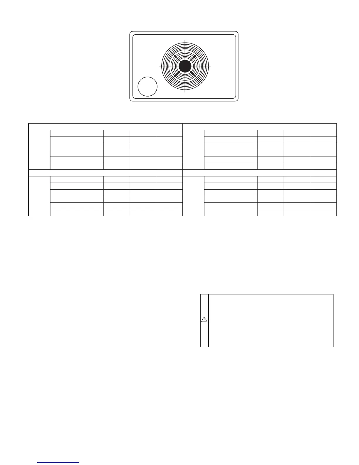
Fig. 4—Corner Weights (in Pounds)
CORNER WEIGHTS (SMALL CABINET) CORNER WEIGHTS (LARGE CABINET)
Model 601A
Unit 303642
Model 601A
Unit 48 60 —
Total Weight 287 291 323 Total Weight 353 418 —
Corner Weight 1 66 67 83 Corner Weight 1 76 90 —
Corner Weight 2 54 55 55 Corner Weight 2 49 58 —
Corner Weight 3 62 63 78 Corner Weight 3 96 114 —
Corner Weight 4 105 106 107 Corner Weight 4 132 156 —
CORNER WEIGHTS (Small Cabinet) CORNER WEIGHTS (Large Cabinet)
Model 602A
Unit 30 36 —
Model 602A
Unit 424860
Total Weight 320 328 — Total Weight 350 375 428
Corner Weight 1 63 64 — Corner Weight 1 75 81 92
Corner Weight 2 74 76 — Corner Weight 2 49 52 60
Corner Weight 3 56 58 — Corner Weight 3 95 102 116
Corner Weight 4 127 130 — Corner Weight 4 131 140 160
C00071
12
43
x
y
—5—
 Loading...