5. Ensure that setscrew engages the flat area on the motor shaft
when tightening.
6. Replace grille.
V. ELECTRICAL CONTROLS AND WIRING
Inspect and check the electrical controls and wiring annually. Be
sure to turn off the electrical power to the unit and install lockout
tag.
Remove access panel to locate all the electrical controls and
wiring. Check all electrical connections for tightness. Tighten all
screw connections. If any smoky or burned connections are
noticed, disassemble the connection, clean all the parts, restrip the
wire end and reassemble the connection properly and securely.
After inspecting the electrical controls and wiring, replace all the
panels. Start the unit, and observe at least one complete cooling
cycle to ensure proper operation. If discrepancies are observed in
operating cycle, or if a suspected malfunction has occurred, check
each electrical component with the proper electrical instrumenta-
tion. Refer to the unit wiring label when making these checkouts.
NOTE: Refer to the Sequence of Operation section as an aid in
determining proper control operation.
VI. REFRIGERANT CIRCUIT
Inspect all refrigerant tubing connections and the unit base for oil
accumulation annually. Detecting oil generally indicates a refrig-
erant leak.
WARNING: System under pressure. Relieve pressure
and recover all refrigerant before system repair or final
unit disposal to avoid serious injury or death. Use all
service ports and open all flow-control devices, including
solenoid valves.
If oil is detected or if low performance is suspected, leak-test all
refrigerant tubing using an electronic leak detector, or liquid-soap
solution. If a refrigerant leak is detected, refer to Check for
Refrigerant Leaks section.
If no refrigerant leaks are found and low performance is suspected,
refer to Checking and Adjusting Refrigerant Charge section.
VII. INDOOR AIRFLOW
The indoor airflow does not require checking unless improper
performance is suspected. If a problem exists, be sure that all
supply- and return-air grilles are open and free from obstructions,
and that the air filter is clean. When necessary, refer to Indoor
Airflow and Airflow Adjustments section to check the system
airflow.
VIII. METERING DEVICE
Refrigerant metering devices are fixed orifices and are located in
the inlet header to the indoor and outdoor coils.
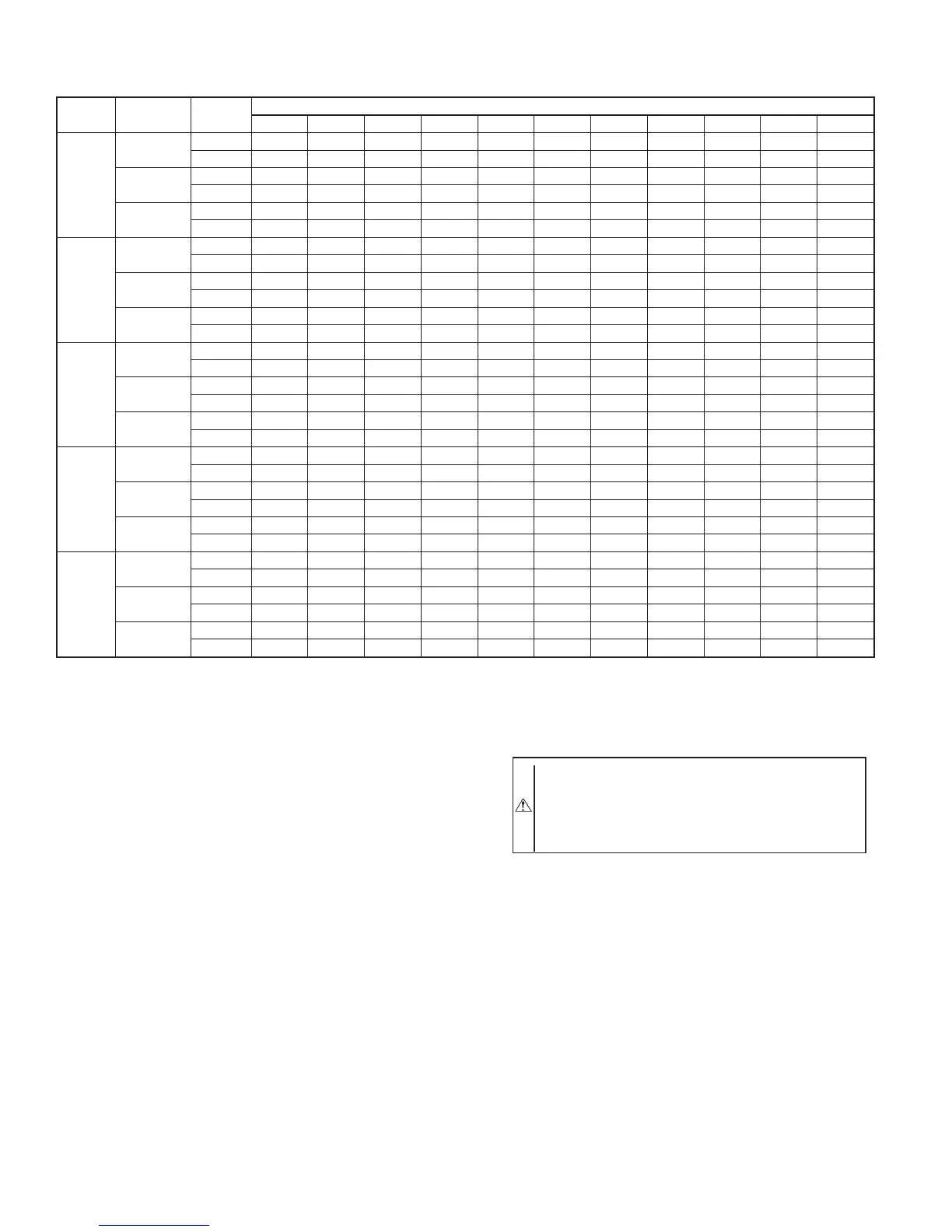
TABLE 8—WET COIL AIR DELIVERY
UNIT 602A 030-060 (DEDUCT 10 PERCENT FOR 208-V)*
UNIT
MOTOR
SPEED
EXTERNAL STATIC PRESSURE (IN. WG)
0.0 0.1 0.2 0.3 0.4 0.5 0.6 0.7 0.8 0.9 1.0
30
Low
Watts276276272--------
Cfm963929781--------
Med
Watts375377371362354350-----
Cfm 1202 1170 1079 976 884 807 -----
High
Watts----469449435428---
Cfm----1174 988 828 718 - - -
36
Low
Watts462451431411394381-----
Cfm 1374 1290 1205 1116 1020 916 -----
Med
Watts523506490471449426-----
Cfm 1500 1408 1301 1190 1082 977 -----
High
Watts-645628610595584575----
Cfm - 1474 1369 1267 1169 1069 962 ----
42
Low
Watts 620 600 586 574 562 548 530 510 487 462 439
Cfm 1662 1621 1581 1540 1496 1447 1392 1331 1263 1186 1103
Med
Watts----686661634606577547517
Cfm----1722 1662 1594 1515 1427 1330 1227
High
Watts-------757730704682
Cfm-------16691577 1486 1402
48
Low
Watts 620 600 586 574 562 548 530 - 487 - -
Cfm 1662 1621 1581 1540 1496 1447 1392 1331 1263 - -
Med
Watts 763 747 729 709 686 661 634 606 577 547 517
Cfm 1917 1868 1822 1774 1722 1662 1594 1515 1427 1330 1227
High
Watts - - - 852 832 809 784 757 730 704 682
Cfm - - - 1982 1914 1839 1757 1669 1577 1486 1402
60
Low
Watts597592578526460452445----
Cfm 2265 2190 2101 2033 1974 1869 1614 ----
Med
Watts 754 730 707 687 671 658 646 630 603 558 486
Cfm 2383 2282 2202 2134 2070 2005 1935 1858 1771 1667 1576
High
Watts 901 876 856 836 813 785 755 723 696 681 687
Cfm 2480 2383 2301 2233 2175 2122 2066 1998 1910 1788 1619
* Air delivery values are based on operating voltage of 230-v or 460-v, wet coil, without filter or electric heater. Deduct filter and electric heater pressure drops to obtain static
pressure available for ducting.
NOTES:
1. Do not operate the unit at a cooling airflow that is less than 350 cfm for each 12,000 Btuh of rated cooling capacity. Evaporator coil frosting may occur at airflows below
this point.
2. Dashes indicate portions of table that are beyond the blower motor capacity or are not recommended.
3. Deduct 10 percent for 208-v.
—20—
 Loading...