7
3. Remove the left-side filter by tip-
ping the filter toward the center
and raising it from the V-shaped
channel in which it rests. (See
Fig. 24 and 25.)
4. Lower filter down next to the
blower and remove from furnace.
5. To remove the right-side filter,
lift from V-shaped channel and
remove through left-side the
same way as left-side filter.
6. Inspect the filter. If torn, replace
the filter.
7. Wash the filter (if dirty) in a sink,
bathtub, or outside with a garden
hose. Always use cold tap water. A
mild liquid detergent may be
used if necessary. Spray water
through the filter in opposite
direction of airflow through the
cross-mesh binding (when
present) side. Allow filter
to dry.
8. Reinstall clean filters with the
cross-mesh binding (when
present) side facing furnace
blower.
9. Replace blower access door and
secure with 2 screws. Turn on
electrical supply to the furnace.
(See Fig. 16.)
*Filters are factory provided with the
furnace. Filters may be field modified
by cutting and folding the frame as
indicated on the filter. Alternate
sizes and additional filters may be
ordered from your dealer.
COMBUSTION AREA
AND VENT SYSTEM
Inspect the combustion area and vent
system before each heating season.
An accumulation of dirt, soot, or rust
UPFLOW FURNACE
FILTER TABLE (IN.)
FURNACE
CASING
WIDTH
FILTER SIZE
FILTER
TYPESide Return
Bottom
Return
14-3/16 (1) 16 x 25 x 1* (1) 14 x 25 x 1 Cleanable
17-1/2 (1) 16 x 25 x 1* (1) 16 x 25 x 1 Cleanable
21 (1) 16 x 25 x 1 (1) 20 x 25 x 1* Cleanable
24-1/2 (2) 16 x 25 x 1* (2) 12 x 25 x 1 Cleanable
DOWNFLOW/HORIZONTAL
FURNACE FILTER TABLE (IN.)
FURNACE
CASING WIDTH
FILTER
SIZE
FILTER
TYPE
14-3/16 (2) 14 x 20 x 1* Cleanable
17-1/2 (2) 14 x 20 x 1* Cleanable
21 (2) 16 x 20 x 1* Cleanable
24-1/2 (2) 16 x 20 x 1* Cleanable
can mean a loss of efficiency and
improper performance. Buildups on
the main burners can cause faulty fir-
ing. This “delayed ignition’’ is charac-
terized by an alarmingly loud sound. If
your furnace makes a loud noise when
the main burners are ignited, shut
down the furnace and call your
servicing dealer.
Use your flashlight and follow these
steps for inspecting the combustion
area and vent system of your furnace:
1. Turn off the electrical supply to
furnace and remove the access
doors. (See Fig. 9, and 10 or 11.)
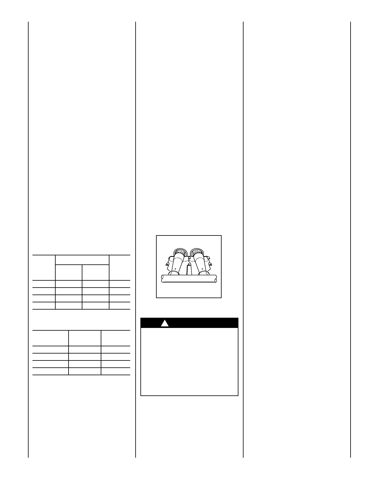
2. Carefully inspect the gas burner
for dirt, rust, or scale. (See Fig.
26.) Inspect the relief box, flue
connection area, and the vent pipe
for rust.
NOTE:
If dirt, rust, soot, or scale accu-
mulations are found, call your servic-
ing dealer. DO NOT OPERATE THE
FURNACE.
3. Inspect the vent pipe for a sag,
holes, or a disconnection. A hori-
zontal vent pipe must slope
upward. If rusty joints or seams,
or signs of water leakages are
found, call your dealer for service.
26
4. Replace the access doors and
restore electrical supply to the
furnace. Be sure bottom door
flange is inside of the furnace cas-
ing. (See Fig. 14 and 15.)
5. Start the furnace and observe its
operation. If possible, watch the
burner flames. Are they burning
WARNING
If holes are found or if the vent
pipe is obstructed or is not
connected, toxic fumes can es-
cape into your home. DO NOT
OPERATE YOUR FURNACE.
Call your dealer for service.
A failure to follow this warning
could result in personal injury
or death.
the air filter for dirt. Check for blocked
return-air or supply-air grilles. Be sure
they are open and unobstructed. If this
direction that the pipe runs (open)? Or is
it at a right angle to the pipe (closed)?
NOTE:
Before proceeding with the
next checks, turn off the electrical
power supply to the furnace. Remove
access doors.
• Is the control knob on the gas
valve turned to the ON position? If
this or the preceding check shows
an interruption in the gas supply,
make sure the gas has not been shut
off for safety reasons. If nothing else
seems to be wrong, follow the startup
procedures found on pages 4 and 5
of this booklet.
• If for some reason the vent is
blocked, the draft safeguard switch will
shut off the furnace. Reset the switch
by pushing the button located on top
of the switch. See page 2 or 3 for switch
location.
If the switch trips a second time, turn
off the furnace and call for service.
•
DOWNFLOW/HORIZONTAL
ONLY
—Check the manual reset aux-
iliary limit switch located on the blower
housing. If the blower motor fails, this
switch will shut off the furnace. Reset it
by pushing the button on the switch. If
it trips again, turn off the furnace and
call for service.
 Loading...