BDA-3 Digital to Analog Converter
7
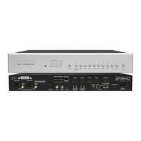
Rear Panel
8. A/C Input
An IEC-320 C14 power inlet provides for
connection of an IEC-320 C13 equipped power
cord. Before connecting the power cord,
check that the voltage rating on the data plate
conforms with your locality. Upon applying
power, the BDA-3 will enter standby mode. See
“Connecting to A/C Power” on page 4.
9. Analog Outputs
Balanced and single ended analog output are
provided via respective le/right pairs of XLR
and RCA jacks. Connect to a preamp or similar
device with a volume control. Do not connect
directly to an amplier that has no volume
control! See “Connecting to a Preamplier” on
page 5.
10. Digital Audio Inputs
Four traditional digital inputs are provided to
receive audio from source components. Each
corresponds to a matching source selector
button on the front panel.
AES/EBU: 110Ω Balanced XLR
S/PDIF 1: 75Ω Coaxial RCA
S/PDIF 2: 75Ω Coaxial BNC
Toslink: Toslink Fiber Optic
11. USB Audio Inputs
Two “Type B” USB Class 2.0 Audio inputs are
available to receive audio from computers,
media servers or other compatible source
components. See “USB Audio” on page 5.
12. HDMI Inputs
Four HDMI inputs are available. 1 through 3 are
each version 1.4a and HDCP version 2.0. Input 4
is HDCP 2.2 compliant. They may receive PCM or
DSD audio, but not surround formats. See “HDMI
Audio” on page 5.
13. HDMI Output
When an HDMI input is selected, the output will
pass video signals along to the next connected
HDMI receiver such as a television or surround
processor. See “HDMI Passthrough” on page 5.
14. Control Interfaces
Three two-way control interfaces are available
to enable BDA-3 control by home automation
systems. See “Remote Control” on page 10 for
connection diagrams and protocol details.
15. Trigger Input
Power/Standby can be toggled from a master
component such as a preamp using this input.
The connector is a standard 3.5mm tip sleeve
commonly referred to as a “mono mini plug”.
Signal should be AC or DC between 3 and 12
volts. When voltage is present at the tip, the
BDA-3 will remain powered on. The BDA-3
powers o when voltage is removed.
16. Status LED
LED lights to indicate the following status:
Red: Standby Green: On
Amber: Starting up Blinking Amber: Updating rmware
17. Data Plate
The data plate indicates hardware version, serial
number, and A/C mains voltage of your unit.
CANADA
BDA-3 D/A CONVERTER
MADE IN
FABRIQUE AU
Ontario
Peterborough
DIGITAL INPUTSANALOG OUTPUTS
RIGHT
SINGLE
ENDED
BALANCED
LEFT
SINGLE
ENDED
BALANCED
CONTROL
HDMI OUT
HDMI 1
HDMI 2
HDMI 3
TRIGGER IN
HDMI 4
AUDIO
USB 2
USB 1
TOSLINK
STATUS
RS232
USB
ETHERNET
SPDIF 2
SPDIF 1
AES/EBU
IEC 320-C14
POWER INLET
8
9
17
12 13
14
16
1510 11