EasyManua.ls Logo

BST BS1801 User Manual

BST BS1801
2 pages
To Next Page IconTo Next Page
Page #1 background imageLoading...
Page #1 background image
3 1/2 Digits Unbeatable Best Buy Multimeters with All-Ranges Protection
OPERATION MANUAL
1. SAFETY RULES
This meter is designed and tested in accordance with EN publication 61010-1, pollution
degree II and installation category (overvoltage category) II 600V.
This meter has been tested according to the following EC Directives
89/336/EEC Electromagnetic Compatibility, EN61326
73/23/EEC Product safety law of Low Voltage Directive, EN61010-1
This meter is designed to be indoor use at temperature 5°C to 40°C and altitude up to
2,000m.
To ensure that the meter is used safely, follow all safety and operating instructions in
this operation manual. If the meter is not used as described in this operation manual,
the safety features of this meter might be impaired.
2. INTERNATIONAL SYMBOLS
Important information
Diode
see manual
Continuity
AC
Ground
DC
Double insulation
3. SPECIFICATIONS
3.1 General Specifications
Display
:
3 1/2 digit LCD with max. reading of 1999.
Polarity
:
Automatic, (-) negative polarity indication.
Zero adjustment
:
Automatic.
Over range indication
:
Only the MSD “1” is displayed.
Power
:
1.5V AAA battery x 3
Dimension
:
85 (W) x 155 (H) x 40 (D) mm.
Net Weight
:
Approx. 250g. (Including battery).
3.2 Electrical Specifications
Accuracies are ± (% of reading + number of least significant digits) at 23°C ± 5°C, <75% RH.
DC Voltage
Range Resolution Accuracy
Input
Impedance
200mV
0.1mV
±(1.0%+3) 10M
600V DC/ACrms
2V
1mV
20V
0.01V
200V
0.1V
600V
1V
AC Voltage
Range Resolution Accuracy
Frequency
(Hz)
200V
0.1V
±(1.2%+3d)
40~400 600V DC/ACrms
600V
1V
DC Current
Range Resolution Accuracy
Overload
Protection
20mA
0.01mA
±(1.2%+3d)
250V DC/ACrms
200mA
0.1mA
10A*
0.1A
±(5.0%+3d)
Resistance
Range Resolution Accuracy
Open circuit
voltage
200
0.1
±(1.2%+3d)
<1.0V
250V DC/AC rms
<30 sec.
2k
0.001k
20k
0.01k
200k
0.1k
2M
0.001M
Capacitance
(BS1902/03)
Range Resolution Accuracy
Test
Volt/Freq
Overload Protection
20µF
0.01µF
±(2.5% + 3d)
<3V/2.5Hz
200µF
0.1µF
Temperature
(BS1903)
Range
Resolution
Accuracy
Overload Protection
-20°C to
+400°C
1°C ±(2.5% + 4°C)
250V DC/AC rms <30 sec.
Diode Test
Test Voltage
Test Current
Overload Protection
<3V Approx. 1.6mA
250V DC/AC rms
<30 sec.
Continuity
Test
Test range
Open circuit
Voltage
Buzzer sounds when
resistance value
<30
<3V
250V DC/AC rms
<30 sec.
Transistor Test
(NPN-PNP)
(BS1901/02/03)
range hFE Value
hFE 0 1000
Phase Sequence
Indication
Range
Phase Sequence Indication
380ACV ±10%
Correct Phase Sequence
Phase Sequence Light “ON”
Live Wire
Verification Voltage
Tested Voltage Range
100~250V
Battery Test
(BS 1901)
Range
Load Resistance
Overload Protection
1.5V load
150
250V DC/AC rms
<30 sec.
12V load
900
Square
Waveform Output
(BS 1901W)
Output Voltage
Frequency
Wave Form
Overload Protection
Approx. 3V 50Hz
Square
Wave
250V DC/AC rms
<30 sec.
* for BS1903 only, use 10A fused current adaptor at 200mV range
4. PANEL DESCRIPTIONS
1. Live wire verification indication light
(BS1901/01W)
2. LCD display
3. Transistor testing socket
(BS1901/02/03); Battery test key
(BS1901W)
4. Multifunction selector
5. HOLD key / Battery test key
6. Phase verification indication light
7. Input terminal
5. OPERATION
!
WARNING
1) When measuring voltage ensure that the instrument is not connected or switched to a
current or resistance, or battery test, or diode/ continuity check range. Always ensure that
the correct terminals are used for the type of measurement to be made.
2) Use extreme care when measuring voltage above 50V, especially from sources where
high energy exists.
3) Avoid making connections to “live” circuits whenever possible.
4) When performing current measurements ensure that the circuit is not “live” before opening
it in order to connect the test leads.
5) Before performing resistance/capacitance measurements or diode test, ensure that the
circuit under test is de-energised.
6) Always ensure that the correct function and range is selected. If in doubt about the correct
range, start with the highest and work downwards.
7) Extreme care should be taken when using the instrument to conjunction with a current
transformer connected to the terminals. High voltage may be produced at the terminals if
an open circuit occurs.
8) Ensure that the test leads and prods are in good condition with no damage to the
insulation.
9) Take care not to exceed the overload limits as given in the specifications.
5.1 DC and AC voltage measurement
1. Connect the black test lead to the “COM” terminal and red test lead to the “V” terminal.
2. Set the multifunction selector to desired DC V or AC V position and connect the test leads
across the source or load under measurement.
5.2 DC current measurement
1. Connect the black test lead to the “COM” terminal and red test lead to the “mA” terminal
for measurement up to 200mA.
2. Set the multifunction selector to desired current range position.
3. Connect the test leads in series with the current source to be measured.
4. When the tested current is above 100mA, the input voltage drop might above 1V; hence,
the test duration cannot exceed 15 seconds!
!
CAUTION: Max. input overload: 250V rms < 20sec.
5.3 Resistance measurement
1. Connect the black test lead to the “COM” terminal and red test lead to the “Ω” terminal.
2. Set the multifunction selector to desired resistance (Ω) range position.
3. Connect the test leads across the circuit to be tested.
!
CAUTION: Ensure that the circuit to be tested is “dead”.
Max. input overload : 250V rms < 20sec.
5.4 Capacitance Measurement (BS1902/03)
1. Connect the black test lead to the “COM” terminal and red test lead to the “
” terminal.
2. Set the multifunction selector to desired Capacitance (C) range position.
3. Connect the test leads across the capacitance to be tested.
!
CAUTION: Ensure that the capacitance to be tested is discharged.
Max. input overload : 250V rms < 20sec.
5.5 Temperature Measurement (with K-Type
Thermocouple) (BS1903)
1. Connect the K-Type Thermocouple cathode (-) to
the “COM” terminal and the anode (+) to “°C”
terminal.
2. Set the multifunction selector to “°C” range
position.
3. Use the K-Type Thermocouple’ probe contact the
object to be tested (Liquid)
4. If the temperature of the environment is sudden
changed or the resettable fuse is in active mode,
the temperature measurement should continue
after 30 minutes; otherwise, the measurement is
not accurate.
5.6 Diode test
1. Connect the black test lead to the “COM” terminal and red test lead to the “
” terminal.
2. Set the multifunction selector to
(same as ) position.
3. Connect the black and red test leads to the cathode (-) and anode (+) ends of the diode
to be tested respectively.
4. Read the forward voltage drop (junction) value from the display. When the forward biased
is open, the display will shows overload ‘1.
!
CAUTION: Max. input overload: 250V rms < 20sec.
5.7 Transistor (NPN/PNP) Test (BS1901/02/03)
1. Set the multifunction selector to hFE position, the meter will display 000
2. Connect the transistor’s pin to the testing socket according to the type of the transistor,
the meter will display transistor’s hFE value, if display abnormal value, it mean wrong
connection is made or the transistor is damage.
!
CAUTION: Max. input overload: 250V rms < 20sec.
!
Question and Answer IconNeed help?

Do you have a question about the BST BS1801 and is the answer not in the manual?

BST BS1801 Specifications

General IconGeneral
BrandBST
ModelBS1801
CategoryMultimeter
LanguageEnglish

Summary

Safety Rules and Compliance

General Safety Precautions

Meter designed and tested per EN 61010-1, pollution degree II, overvoltage category II 600V.

EC Directives Compliance

Meter tested according to EC Directives 89/336/EEC (EMC) and 73/23/EEC (Product Safety).

Operating Environment Guidelines

Designed for indoor use at 5°C to 40°C and altitude up to 2,000m.

Safe Usage and Manual Adherence

Ensure safe usage by following all instructions in this manual.

Product Specifications Overview

General Specifications

Details display type, polarity, zero adjustment, over range, power, dimensions, and net weight.

DC Voltage Measurement Specs

Specifications for DC voltage measurement including range, resolution, accuracy, input impedance, and overload protection.

AC Voltage Measurement Specs

Specifications for AC voltage measurement including range, resolution, accuracy, frequency, and overload protection.

DC Current Measurement Specs

Specifications for DC current measurement including range, resolution, accuracy, and overload protection.

Resistance Measurement Specs

Specifications for resistance measurement including range, resolution, accuracy, and overload protection.

Capacitance Measurement Specs

Specifications for capacitance measurement including range, resolution, accuracy, test voltage/frequency, and overload protection.

Temperature Measurement Specs

Specifications for temperature measurement using K-Type Thermocouple, including range, resolution, accuracy, and test voltage.

Diode and Continuity Test Specs

Specifications for diode test and continuity test including test voltage, current, and overload protection.

Transistor Test Specs

Specifications for transistor testing including range, hFE value, and overload protection.

Phase Sequence Indication Specs

Specifications for phase sequence indication including range, verification voltage, and overload protection.

Live Wire Verification Specs

Specifications for live wire verification including range, tested voltage, and overload protection.

Battery Test Specs

Specifications for battery testing including range, load voltage, frequency, waveform output, and overload protection.

Panel Description and Operation

Panel Components Identification

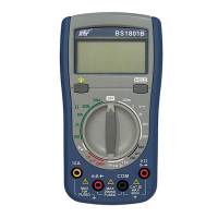
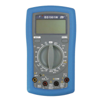
Description of panel components including display, terminals, selector, and indicators.

DC and AC Voltage Operation

Instructions for measuring DC and AC voltages, including terminal connections and range selection.

DC Current Measurement Operation

Instructions for measuring DC current, including series connection and input voltage drop considerations.

Resistance Measurement Operation

Instructions for measuring resistance, emphasizing de-energizing the circuit and correct range selection.

Capacitance Measurement Operation

Instructions for measuring capacitance, highlighting the need to discharge the capacitor before testing.

Temperature Measurement Operation

Instructions for measuring temperature using a K-Type Thermocouple, including probe contact and environmental changes.

Diode Test Operation

Instructions for performing a diode test, focusing on polarity and reading the forward voltage drop.

Transistor Test Operation

Instructions for testing transistors (NPN/PNP) using the hFE socket and interpreting the hFE value.

Phase Sequence Verification

Procedure for verifying the phase sequence of a three-phase power supply using test leads and indicator.

Live Wire Verification

Procedure for verifying the presence of live voltage using the dedicated function and indicator light.

Continuity Test Operation

Instructions for continuity testing, noting the audible buzzer activation below 30 ohms.

Battery Test Operation

Instructions for testing batteries (1.5V/12V), including measurement with and without load, and calculating internal impedance.

Square Waveform Output

Instructions for generating a square waveform output for testing purposes.

AC Current Measurement with Clamp

Procedure for measuring AC current using an optional add-on clamp accessory.

Maintenance and Service Information

Battery Replacement Procedure

Step-by-step guide for safely fitting and replacing the meter's battery.

Cleaning Instructions

Guidelines for cleaning the meter's case using a soft cloth and mild cleanser.

Included Accessories

List of standard accessories provided with the multimeter packaging.

Warranty Conditions

Details on warranty coverage, exclusions, and procedures for returning the product for service.

Service and Technical Assistance

Guidance on troubleshooting and contacting for technical support or service.

Related product manuals