Do you have a question about the BST BS1901W and is the answer not in the manual?
Covers safety rules, international symbols, general and electrical specifications.
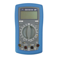
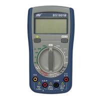
Identifies panel parts and covers basic measurement procedures like voltage, current, resistance.
Details continuity, battery tests, waveform output, AC current, battery replacement, and cleaning.
Lists included accessories, warranty conditions, and service/technical contact.
This document describes a 3 1/2 Digits Unbeatable Best Buy Multimeter with All-Ranges Protection, designed for indoor use at temperatures between 5°C and 40°C and altitudes up to 2,000m. It complies with EN publication 61010-1, pollution degree II, and installation category (overvoltage category) II 600V, as well as EC Directives 89/336/EEC (Electromagnetic Compatibility, EN61326) and 73/23/EEC (Low Voltage Directive, EN61010-1). Users must follow all safety and operating instructions to ensure safe operation and prevent impairment of safety features.
The multimeter offers a wide range of measurement functions, including DC Voltage, AC Voltage, DC Current, Resistance, Diode Test, Continuity Test, Phase Sequence Verification, Live Wire Verification, Battery Test, and Square Waveform Output.
DC and AC Voltage Measurement: To measure DC or AC voltage, connect the black test lead to the "COM" terminal and the red test lead to the "V" terminal. Set the multifunction selector to the desired DC V or AC V position, then connect the test leads across the source or load under measurement. Extreme care should be taken when measuring voltages above 50V, especially from high-energy sources, and connections to "live" circuits should be avoided whenever possible.
DC Current Measurement: For DC current measurement, connect the black test lead to the "COM" terminal and the red test lead to the "mA" terminal for measurements up to 200mA. Set the multifunction selector to the desired current range position and connect the test leads in series with the current source. If the tested current exceeds 100mA, the input voltage drop may exceed 1V, and the test duration should not exceed 15 seconds. The maximum input overload is 250V rms for less than 20 seconds. Ensure the circuit is not "live" before opening it to connect the test leads.
Resistance Measurement: To measure resistance, connect the black test lead to the "COM" terminal and the red test lead to the "Ω" terminal. Set the multifunction selector to the desired resistance (Ω) range position and connect the test leads across the circuit to be tested. It is crucial to ensure that the circuit under test is "dead" before performing resistance measurements. The maximum input overload is 250V rms for less than 20 seconds.
Diode Test: For diode testing, connect the black test lead to the "COM" terminal and the red test lead to the "+" terminal. Set the multifunction selector to the diode test position (indicated by "++" or ")))"). Connect the black and red test leads to the cathode (-) and anode (+) ends of the diode, respectively. The forward voltage drop (junction) value will be displayed. An overload '1' will be shown if the forward-biased diode is open. The maximum input overload is 250V rms for less than 20 seconds. Ensure the circuit under test is de-energized.
Continuity Test: To perform a continuity test, connect the black test lead to the "COM" terminal and the red test lead to the ")))" terminal. Set the multifunction selector to the continuity position (indicated by ")))" or "++"). Connect the test leads across the circuit to be tested. A buzzer will activate if the resistance value is less than 30Ω. The maximum input overload is 250V rms for less than 20 seconds.
Phase Sequence Verification: For phase sequence verification, connect the red test lead to the "c" terminal, the black test lead to the "b" terminal, and the yellow test lead to the "a" terminal. Set the multifunction selector to the "600V~/abc" range. Connect the yellow/black/red test leads to the three-phase contact points. If the phase sequence LED lights on, it indicates a correct phase sequence. If the LED remains off, swap the black (b) and red (c) test leads. If it still remains off, there might be a missing phase or a wrong connection, in which case the Live Wire Verification function should be used to verify each phase again.
Live Wire Verification: To verify live wires, connect the red test lead to the "" terminal and the black test lead to the "COM" terminal. Hold the black test lead (without touching the test pin and keeping hands away from the finger guard). Set the multifunction selector to the "600V~/abc" range. Use the red test lead to contact the live wire to be tested. The Live Wire Verification light will turn on if a live wire is detected.
Battery Test: To test a battery, connect the black test lead to the "COM" terminal and the red test lead to the "batt." terminal. Set the multifunction selector to the "1.5V or 12V" range. To measure the battery voltage without loading (V1), connect the test leads to the battery (red to cathode (+), black to anode (-)). If the display shows "---", it means the red test lead is connected to the anode (-). To measure the battery voltage with loading (V2), press the "BATT." key. The meter presets an internal loading Ro of 9000 for 12V and 1500 for 1.5V. The internal impedance (Ri) of the battery can be calculated using the formula: Ri = ((V1-V2) × Ro) / V2.
Square Waveform Output: For square waveform output, connect the black test lead to the "COM" socket and the red test lead to the "ma" socket. Set the function selector to the square waveform position and connect the test leads across the device under test.
Measuring AC Current with an Add-on Clamp (Optional): Connect an add-on clamp anode (-) to the "COM" terminal and cathode (+) to the "" terminal. Clamp the tested wire with the clamp head, and the AC current value will be shown on the display.
The device features a 3 1/2 digit LCD with a maximum reading of 1999 and automatic negative polarity indication. Zero adjustment is automatic. An "1" on the MSD indicates an over-range condition. It is powered by three 1.5V AAA batteries. The multifunction selector allows easy switching between different measurement modes and ranges. A HOLD key is available to freeze the displayed reading. The device includes a live wire verification indication light and a phase verification indication light for enhanced safety and ease of use.
Battery Replacement: Before attempting battery removal or replacement, it is crucial to disconnect test leads or probes from any energized circuits to avoid shock hazards. To replace the battery:
Cleaning: Periodically wipe the case with a soft, damp cloth and a mild household cleanser. Do not use abrasives or solvents. Ensure that no water gets inside the equipment to prevent possible shorts and damage.
Warranty and Service: The meter is guaranteed against material faults or manufacturer's defects for one year from the date of sale. Faulty parts may be replaced, with the manufacturer reserving the right to repair or replace the product. The customer is responsible for the outward transport costs when returning the meter for service. Returns must be agreed upon in advance with the consignee and should include a clear note explaining the reasons for return, using only the original packing. Damage caused by shipment without original packaging will be charged to the consignor.
The warranty does not cover accessories, batteries, repairs due to unsuitable use, incompatible accessories, incorrect shipping, unauthorized servicing, modifications without explicit authorization, or adaptations not provided for in the manual.
If the meter does not work properly, users should first check the battery condition and test leads. If the issue persists, verify that the operating procedure aligns with the manual. For technical assistance, contact the provided service channels. The manufacturer reserves the right to modify specifications and prices as part of ongoing product development.
| DC Voltage Range | 200mV/2V/20V/200V/600V |
|---|---|
| AC Voltage Range | 200V/600V |
| DC Current Range | 200μA/2000μA/20mA/200mA/10A |
| Diode Test | Yes |
| Continuity Buzzer | Yes |
| Data Hold | Yes |
| Power Supply | 9V Battery (6F22) |
| Display | LCD |
| Resistance Range | 200Ω/2kΩ/20kΩ/200kΩ |