1.0
Web guiding system EKR 1500 EDV-No.: V3D.010.01.03 Chapter: 1.0
with analogue sensors and CCD 2004 Date: 12.04.2011 Page: 4/5
1.5 Signification of the LED´s on the front panel
* The LED’s on the keys indicate the switched-on function.
* The blinking of LED’s AUTO (1) , MAN (2) , S-C (3) , SET UP (6) or LED- arrays 10 - 14
and/or 15 - 19 indicate a fault message. Simultaneously, the OK-relay is switched-off. (see
also chapter 8)
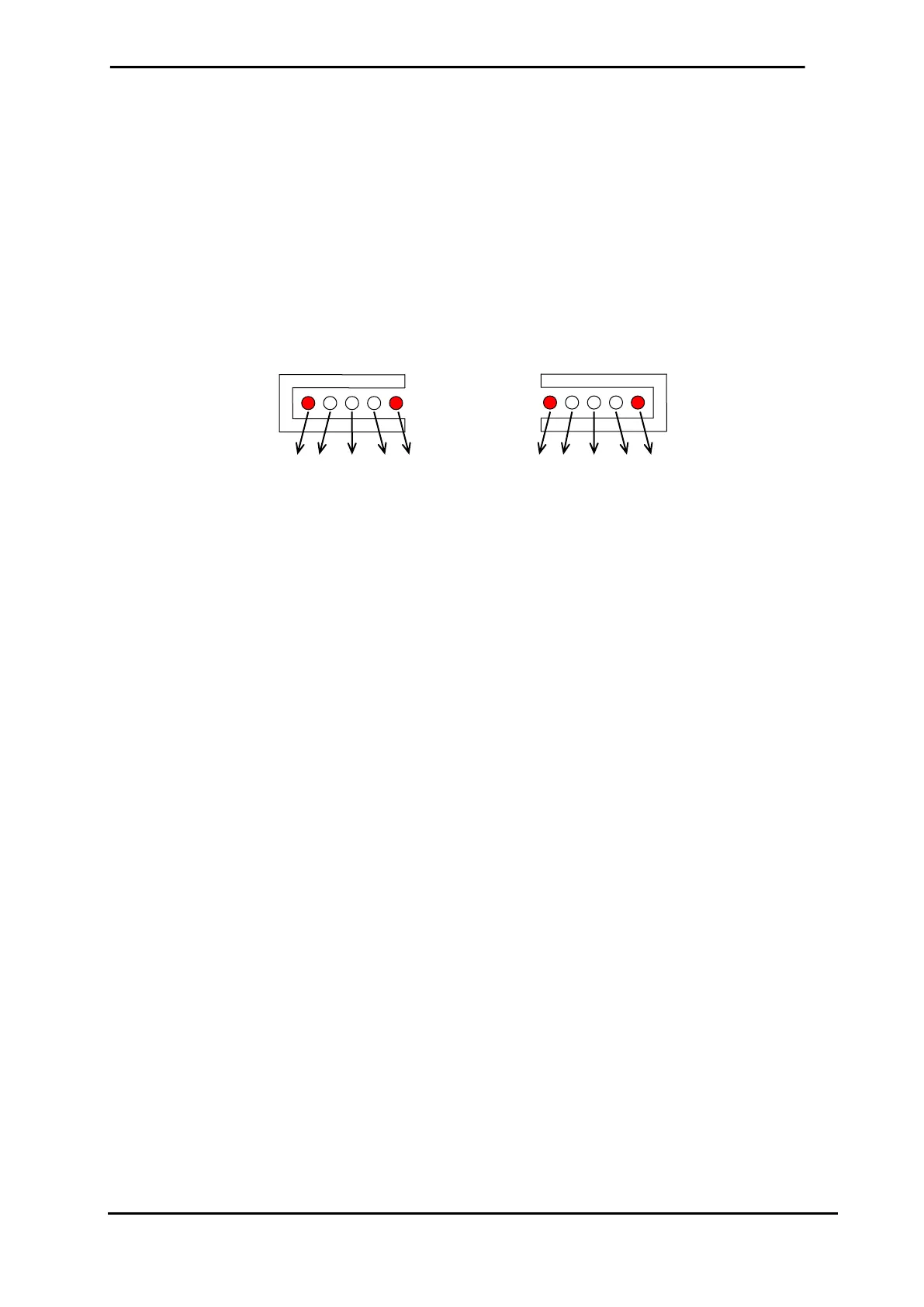
* LED-No. 10, 14,15 and 19 (red) signalise the limits of the measuring band of the sensors.
* LED-No. 12 and 17 (green) signalise the center of the measuring band of the sensors.
* additional indications of the LEDs for gain and shifting of the guiding point see points 5.10.3,
6.1.3, 6.2 and 6.3.
10 11 12 13 14 15 16 17 18 19
 Loading...