BT Home Monitor ~ 8th Edition ~ 26th March ’03 ~ 5296
Step 6 – Completing Installation
INPUTTING YOUR PROPERTY
IDENTIFICATION NUMBER
In the previous step, you will have received your
Property ID Number. This should now be input
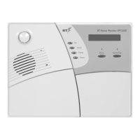
into your BT Home Monitor VP1000 Control
Panel. You will need to:
PRESS DISPLAY
Until the display shows
SYSTEM PROFILE.
Enter default PIN 2580.
Until display shows
COMMS SETTINGS.
Until display shows
PROPERTY ID NO.
Insert your Property ID.
Twice then <OK> to return to
READY.
CONNECTING YOUR TELEPHONE LINE
Now take the Phone Cable and insert the clear jack
into the back of the Control Panel. Insert the
doubler into your telephone socket. Fig 12.
Fig 12
WALL MOUNTING THE CONTROL PANEL
• Turn the panel over and push the bracket
downward to release. Fig 13.
• Lift the bracket arms and detach from panel.
Fig 13.
• Using the bracket as a guide, mark the
mounting surface with the three drilling holes
which can be found on the left, right and
bottom of the bracket.
• The large circle in the bracket is for the tamper
retainer washer, which is a fourth hole which
needs to be marked. Fig 14.
Fig 14.
• The tamper retainer washer can be found in
the mounting equipment and needs to be
inserted into the large circle and then screwed
to the bracket and the wall. Using the tamper
retainer washer will ensure that if there is an
attempt to force your Control Panel off the wall
a tamper alert will be set off.
• Drill the four holes
.
• Insert wall plugs and fasten the bracket to the
mounting surface with the screws provided.
• You can now slot the Control Panel into the
bracket.
NEXT
SHOW / OK
NEXT
SHOW / OK
SHOW / OK
NEXT
SHOW / OK
SHOW / OK
 Loading...