What to do if BTG SBT-2400 Transmitter output doesn't match actual consistency?
K
Kimberly HernandezAug 4, 2025
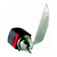
If the BTG SBT-2400 Transmitter output doesn't correspond to actual consistency, it could be due to cabling problems. Verify that all cables are connected correctly and in good condition. Another potential cause is a damaged blade. Inspect the blade, and if damaged, replace it, then perform a basic force calibration. If issues persist, the measuring unit may be damaged. Check if the transmitter responds to calibration using different weights. If there are no changes in the output, replace the measuring unit.
D
darren95Aug 11, 2025
Why BTG SBT-2400 Transmitter measures correctly but the display doesn't respond?
J
Jessica WheelerAug 11, 2025
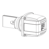
If the BTG SBT-2400 Transmitter measures correctly, but the display doesn't respond, the issue might be a faulty junction box, circuit board, or wiring. First, verify that all wires are properly connected by opening the housing and checking all wire connections. If the wiring is correct, inspect the junction box. If the fault is not found in the junction box, replace the electronics unit.
W
William ValenciaAug 19, 2025
What to do if BTG SBT-2400 Transmitter output doesn't match lab consistency values?
A
awoodAug 19, 2025
If the BTG SBT-2400 Transmitter output doesn't correspond to lab consistency values, it might need calibration. Remove the transmitter from its location and mount it in its calibration stand to perform a basic force calibration. A damaged blade can also cause this issue; inspect and replace it if necessary, followed by recalibration. If the problem persists, the measuring unit could be damaged. Check the transmitter's response to calibration using different weights, and if there's no change, replace the measuring unit.
M
Mr. Charles HaleAug 27, 2025
How to troubleshoot HART interface on BTG SBT-2400 Transmitter?
M
Morgan RobinsonAug 27, 2025
If the BTG SBT-2400 Transmitter operates normally except for the HART interface, the transmitter software might not be responding. Reboot the transmitter by disconnecting the cable, waiting 10 seconds, and then reconnecting it. If HART still doesn't work, the electronics unit could be faulty. Verify that the measuring resistor is at least 250 ohm, the supply voltage is adequate, and the terminal voltage is at least 11V. If HART operates at some signal current, try changing the cable. If that doesn't work, or HART doesn't operate at all, replace the electronics unit.