Do you have a question about the BTG TCT-2301 and is the answer not in the manual?
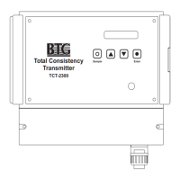
Overview of the TCT-2301 in-line transmitter for measuring total consistency in pulp suspensions.
Detailed specifications including type, manufacturer, principle, range, accuracy, and repeatability.
Explanation of the patented Peak Method for measuring total consistency using light scattering.
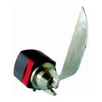
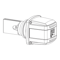
Describes the system components, probe, electronics box, and hand-held terminal connection.
Provides detailed physical dimensions for the TCT-2301 electronics box and probe assembly.
Explains the meaning of various symbols and codes on the device's type sign.
Declares compliance with relevant European directives and standards for the product.
Outlines essential safety precautions for installation, handling, and service personnel.
Provides safety guidelines specific to the TCT-2301 transmitter installation and operation.
Detailed instructions for physically installing the transmitter probe into the process line.
Critical guidance on selecting the optimal installation point for accurate measurements.
Procedures for installing the electronics box, including site selection and connections.
Detailed steps for connecting the probe's optical fiber to the electronics box connector.
Guides on planning and implementing the installation, including pre-checks.
Instructions to check the product for shipping damage before installation.
Emphasizes proper installation for reliable service and maximum operating life.
Specifies the necessary space for probe removal and operator access during installation.
Step-by-step guide for mounting the ball valve assembly onto the pipe.
Instructions for correctly positioning and securing the probe within the valve assembly.
Advice on selecting an optimal location for the electronics box for convenient access and protection.
Information on the design features of the electronics box, including enclosure and internal protection.
Specifies recommended wire types, shielding, and cable diameters for external connections.
Instructions for safely connecting the main power supply to the electronics box.
Details on connecting input/output signals and setting measuring ranges.
Instructions for installing the optional PCD-1000 probe cleaning system.
A final checklist to ensure all installation steps are completed before powering up the system.
Guides on initial setup, connecting the hand-held terminal, and basic operation.
How to set the transmitter identification name (TAG) and serial number using the terminal.
Explains how to select and configure different measuring ranges for calibration.
Steps to choose between mg/l and % as the measuring unit.
Guidance on specifying the consistency values for 4 mA and 20 mA output signals.
Essential procedure to establish a zero reference value using clear water.
Detailed steps for performing the initial clear water adjustment for accurate measurements.
How to choose preset calibration curves based on fiber types for optimal measurement.
Instructions for setting the correct angle of the measuring gap relative to the flow for stable signals.
Comprehensive guide on calibrating the transmitter for accurate consistency readings.
Important considerations before performing calibration, including installation and setup checks.
Lists the prerequisites that must be met before calibration can be performed.
Guidelines for taking representative laboratory samples for accurate calibration.
Step-by-step instructions for performing a single-point calibration using laboratory samples.
Explains how to perform multi-point calibration for improved accuracy across the span.
How to manually enter calibration constants (K0 and K1) if needed.
Information on storing and managing collected calibration data in a table.
How the calibration curve is displayed and interpreted, including constants and correlation factor.
Covers additional functionalities beyond basic operation and calibration.
How to adjust the time constant to stabilize the output signal and its impact on accuracy.
Procedures for configuring alarm thresholds for various parameters like consistency and temperature.
Methods for adjusting the zero point of the calibration based on lab samples or detected deviations.
Function for manually loading specific probe signal settings for calibration data.
Guidance on evaluating, documenting, and backing up calibration data for troubleshooting.
How to view and analyze the output signal trend over time to assess stability.
Steps for printing calibration settings and data using a compatible printer.
Instructions for storing transmitter settings and calibration data on a memory card.
How to use PC software to document calibration data and transmitter settings.
Overview of the display and buttons on the electronics box for basic adjustments.
Describes the electronics box display capabilities and limitations compared to the hand-held terminal.
Outlines the navigation structure of the electronics box display menu.
Detailed steps for modifying settings and collecting samples via the electronics box display.
Introduction to the SPC-1000 hand-held terminal used for configuration and monitoring.
Details the different power supply options for the hand-held terminal.
How to set up and manage security codes to prevent unauthorized transmitter adjustments.
Information about digital communication capabilities using the HART protocol.
Overview of BTG's ISO 9001 certification and approach to product quality and testing.
Guidelines for checking transmitter accuracy against laboratory samples in operational mode.
Recommendations on the frequency of calibration checks based on transmitter usage.
Regular and long-term maintenance tasks required for the transmitter, depending on conditions.
Explains the overall operating principle of the TCT-2301, including signal flow and components.
Troubleshooting and maintenance procedures for the electronics components of the transmitter.
A table listing common symptoms, probable causes, and solutions for electronics issues.
Explains the meaning and status of the LEDs on the electronics card.
Details the functions of various test points and components on the electronics card.
Step-by-step instructions for safely replacing a faulty electronics card.
Procedures for replacing the 24V power supply unit if it malfunctions.
Instructions for replacing the front panel, including display and buttons.
How to verify the analog output signal using a digital multimeter.
Detailed steps for recalibrating the analog output signal to ensure accuracy.
Procedures to verify proper communication between the SPC-1000/A and the transmitter.
How to check and configure the input signals for selecting measuring ranges.
Method for changing the measuring range via hardware inputs (short circuits).
Method for changing the measuring range using the SPC-1000 software interface.
Steps to verify the functionality of the alarm output signal and LED indicators.
Procedures related to servicing the probe and its associated valve assembly.
Step-by-step instructions for safely removing the probe from the ball valve assembly.
Guidance on cleaning the probe's measuring gap and checking the clear water value.
Instructions for replacing the probe, including fiber connection and recalibration steps.
Procedure for replacing the seals within the ball valve assembly.
Detailed steps for correctly inserting the probe back into the valve assembly.
Information and troubleshooting related to the software used with the transmitter.
How to check the software versions of the sensor card and application.
Overview of troubleshooting functions available through the SPC-1000 and printouts.
Accessing the instrument's alarm and error log for troubleshooting purposes.
Explains common error messages from the SPC-1000 and their probable causes/solutions.
Methods for evaluating calibration results by studying curves, constants, and correlation factors.
A general fault tracing procedure for issues not covered elsewhere.
Procedures for removing, disassembling, and reassembling the optional probe cleaning system.
A detailed list of parts for the probe assembly, including part numbers and descriptions.
A breakdown of the components that make up the valve arrangement for probe mounting.
Parts list for the main TCT-2301 unit, detailing electronics box and internal components.
A list of spare parts for the optional PCD-1000 probe cleaning device.
Lists available accessories such as hand-held terminals, cables, and software.
| Brand | BTG |
|---|---|
| Model | TCT-2301 |
| Category | Transmitter |
| Language | English |