5 Putting into operation
20 K-355 Operation Manual, Version G
The instrument cable must be well attainable at all times.
Make sure that no electric sparks form in the instrument or its surroundings as they might damage
the instrument.
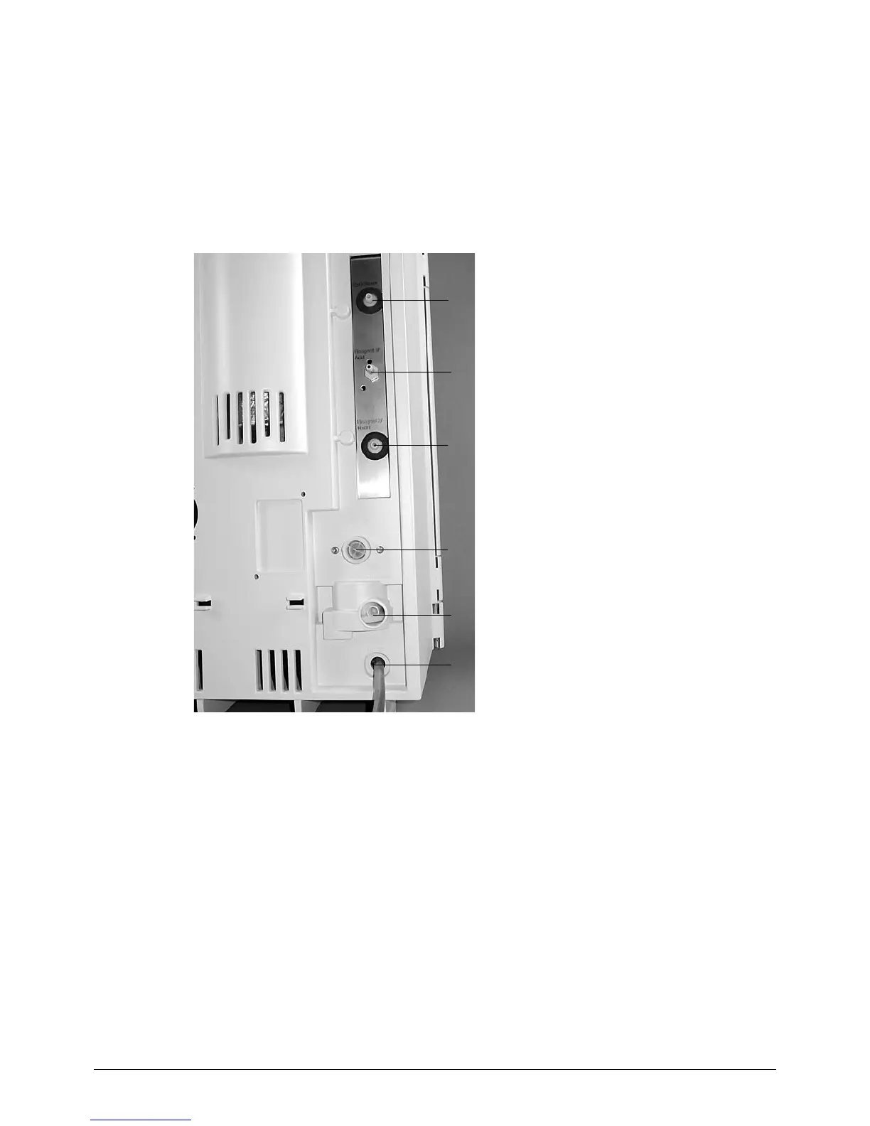
5.3 Reagent and water connections
a
b
c
d
e
f
a H
2
O inlet (for steam generator) from tank
b Reagent 1 inlet (water or acid)
c Reagent 2 inlet (NaOH)
d Cooling water inlet
e Cooling water outlet
f Drain to waste
Fig. 5.2: Reagent and water connections
All pumps are self-priming, no overpressure is necessary at the tanks.
5.3.1 Cooling water connection
Secure the cooling water hose with a hose clamp on both the instrument and the water connection
side. The water pressure should be at a maximum of 4 bar. The built in valve reduces the water flow to
1.2 liters per minute.
The flanged screw coupling for the water connection has a standard screw thread of G ¾”.
5.3.2 Drainage of cooling water
Place the drain hose for the cooling water directly into the drain. For this purpose, shorten the silicone
hose to the optimal length. The drain hose should not show any kinks, sharp bends and/or siphoning
effect. Prevent flooding inside and outside the instrument by securing the drain hose.